The vortex flow meter operates on the physical principle of the Karman vortex street.
When a fluid flows pass a bluff body, vortices are alternately forced on the side of that body and then detached or shed by the flow.
The frequency of vortex shedding is proportional to the mean flow velocity and therefore the volumetric flow (with Reynolds > 4000) St = Fd/V
Vortex frequency = St.v/d
St = strouhal number (dimensionless)
v = velocity fluid (m/s)
d = width of bluff body (m)
Alternating pressure changes caused by the vortex are transmitted via a lateral port (sensor) into the bluff body.
The sensor detects the pressure pulses and converts these into electrical signals.
They are typically available in flange sizes from ½ inch to 12 inches.
In gas services frequencies are about 10 times higher than in liquid applications.
The proportionality between object width (d) and vortex street wavelength {(l) – (lambda)} is called the “strouhal number” (S), approximately equal to 0.17
ls = d
l » d/0.17
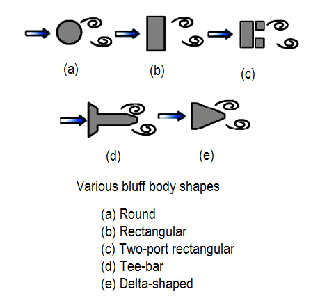
The vortex flow meter has a bluff body (for obstruction) inside it to create vortices. By measuring these vortices, we can measure the equivalent flow rate.
We have different types of sensors available to measure these vortices.
They are
Image Courtesy : E & H
Thermostats are using (negative temperature co-effective)
The majority of vortex meter use piezoelectric or capacitance type sensor. to detect the pressure oscillation around the bluff body.
The strouhal number and bluff body width and the cross sectional area of the flow meter are all constants (which is defined as “K”) the equation becomes
Q = F/K
“K” factor can be defined as pulses per unit volume such as pulses per gallons, pulses per liter, pulses per cubic feet, therefore one can determine flow rate by counting the pulses per unit time.
Vortex frequencies range from one to thousands of pluses per second depending upon the flow viscosity the character of the process fluid and the size of meter.
The pipe Reynolds number should be above 30,000 minimum. This means vortex meters can only be used on low viscosity liquids. High viscous fluids (>3 pa.s (30cp)) and slurries are not recommended applications. (higher viscous having head loss)
The vortex shedding meter provides a linear digital output signal without the use of separate transmitter or converters.
There is no drift because this is a frequency system
The calibration of the meter is virtually independent of the operating conditions (viscosity, density, pressure, temperature and so on) whether the meter is being used on gas or liquid.
Low pressure (low density) gases do not produce a strong enough pressure pulse, especially if fluid velocity are low (if use the meter will be poor and low flows will not be measurable.
Vortex meter accuracy is based on the known value of the meter factor (K- factor).
If you liked this article, then please subscribe to our YouTube Channel for Instrumentation, Electrical, PLC, and SCADA video tutorials.
You can also follow us on Facebook and Twitter to receive daily updates.
Read Next:
The conveyor sorting machine is widely used in the packing industries using the PLC program…
Learn the example of flip-flop PLC program for lamps application using the ladder logic to…
In this article, you will learn the STAR DELTA programming using PLC controller to start…
Lube oil consoles of rotary equipment packages in industrial process plants are usually equipped with…
Rotating equipment packages such as pumps, compressors, turbines need the lube oil consoles for their…
This article explains how to blink lights in ladder logic with a detailed explanation video…

