Cable tray systems are alternatives to wire ways and electrical conduit, which completely enclose cables.
Cable trays are capable of supporting all types of wiring: such as
- High Voltage Power Lines.
- Power Distribution Cables
- Control cables
- Telecommunication cables
- Fiber Optical Cables
Purpose:
Cable trays are components of support systems for power and communications cables and wires.
A cable tray system supports and protects both power and signal cables and facilitates upgrading, expanding, reconfiguring, or relocating networks.
Most of the cable tray systems are open, allowing efficient heat dissipation and easy access for replacement and repairs. Although typically suspended from ceilings or affixed to walls, some cable tray systems are suitable for underfloor use.
Types of Cable Trays:
The following are popular cable tray types.
- Ladder-type
- Perforated type
- Solid bottom type
- Wire mesh
- Channel type
An engineer or designer will usually specify the type of cable tray that has the features to suit the project. It depends on the situation and the environment.
Read: Instrumentation Cables
The selection of cable tray depends upon the number of cables, size, spacing, and weight of cable in the tray.
Ladder Cable Tray
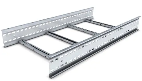
Ladder Cable tray has two side rails connected by rungs. This type of cable tray is effective because the ladder rungs give you easy accessibility to the cables, from the top or bottom.
The rungs of the ladder cable trays provide convenient anchors for tying down the cables in the non-horizontal cable tray runs or where the positions of the cables must be maintained in the horizontal cable tray runs.
Perforated Cable Tray
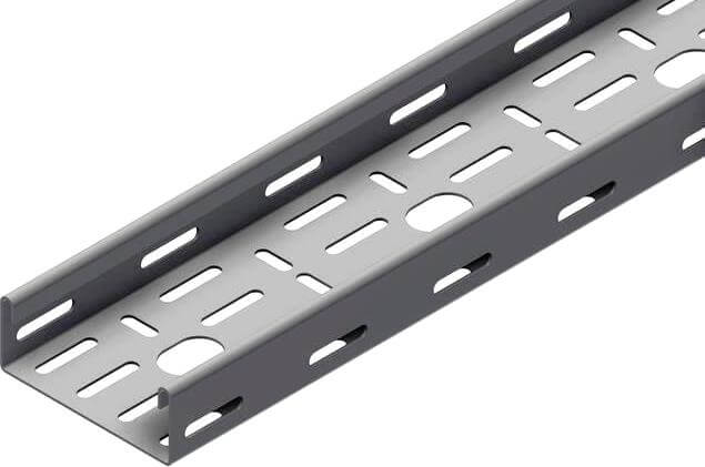
Perforated cable tray Consists of a ventilated bottom with side rails. It provides more support to cables than the ladder-type,
Solid-bottom Cable Tray
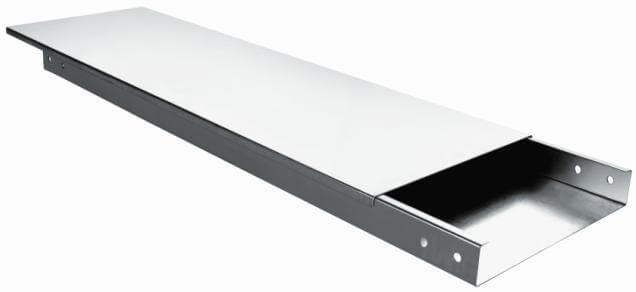
Solid-bottom Cable trays for fiber-optic cable installations where drooping of cables may affect system performance, solid-bottom (non-ventilated) cable trays are preferred.
However, the main reason for selecting solid-bottom trays is a concern for electromagnetic/ radio-frequency interference protection.
Wire Mesh Cable Tray
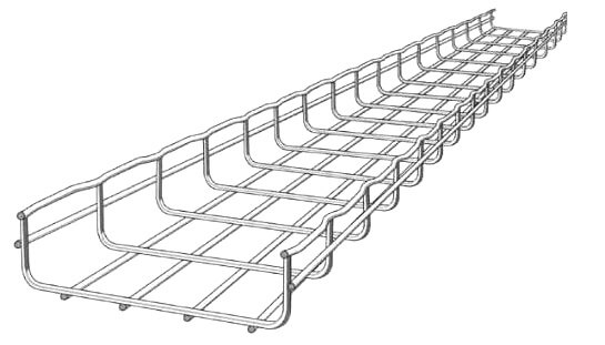
Wire mesh cable tray, also called basket cable tray, is a kind of cable tray made of stainless steel wires by welding wires together, forming a basket-like mesh
Cable Trays are mainly used for low voltage, telecommunication, and fiber optic cables supported on short spans.
Channel Cable Tray
Channel cable tray nothing more than a metal tray that can be used for very small cable installations.”
Materials
1. Metallic
Aluminum: Resists corrosion; excellent strength-to-weight ratio. Aluminum is most commonly used because it is lightweight.
Steel: Electric shielding; low thermal expansion
Stainless steel: Superior corrosion resistance; withstands high temperatures.
2.Non-Metallic
Fiberglass: Nonconductive; resists corrosion; lightweight
Precautions:
The most important issue is to ensure that the bend radius for the fiber-optic or coaxial cable is maintained within the standards.
Combustible dust and clutter may accumulate if the trays are not routinely checked and kept clean.
Advantages:
Less expensive: One of the big advantages that using a cable tray has that it costs a lot less than other methods of protecting wiring on the production floor.
Maintenance: Cable are instantly visible for maintenance checks, changing of cables is easy because cables can enter or exit the tray at any point of the system.
Safety: Regular housekeeping is important for safety, as cable trays are often installed in hard to reach places.
Disadvantages:
The solid bottom cable tray system has a disadvantage. In that moisture can build up in the cable trays.
Read Next:
- Uses of Multi Cable Transit
- Cable Gland Questions and Answers
- What are Fieldbus Cables?
- Cables with Ferrites
- Instrumentation Cable Trays








Tray may refers to cable tray or tubing tray.
Cable Tray is used to support large number of cable or tubing between two points. Tray material shall be selected according to environmental and installation conditions.
Several types of material are available such as 316 SS, GRP, galvanized steel and aluminium.
The design of tray is recommended to be perforated to prevent liquid or droplet trapped. Tray shall be protected with tray cover for installation where possibility of fallen objects such as liquid spill, debris, etc, on the tray may exist.
Besides supported by tray, cable may also be support by ladder for larger cable or by channel for fewer number of cable.
Cable Tray Systems refer to Cable trays, Fittings and its accessories to connect the fittings & components.
Types of Cable Tray Fittings
Straight Tray (Standard Length is 3 meter)
Bend ( Used for Directional change in the horizontal plane – turns the route right or left)
Elbow/riser (Used for directional change in the vertical direction – turns up or down)
Tee (Used to take a new branch from the existing route)
Reducer (To modify the width of cable tray systems based on cable runs)
Cross (It’s similar to four road junction, which allows the intersection of two tray routes)
Splice Plates (used to connect two individual fittings)
Adjustable splice plates (purpose is similar to hinges indoors, we can adjust the angle as required while connecting the two fittings)
Nuts & Bolts (Used to connect two fittings)
Other Factors that are inevitable in cable tray routings:
1) Bending Radius of BEND, ELBO, TEE, CROSS
2) Tray Height
3) Equal or Unequal tee & cross
4) Angle for bend & elbow (30,45,60,90 – standard angle)
5) Supporting & Installation of Cable Trays.
6) Load / Weight capability per meter length.
7) Cable tray loading & cross-section list.
Good Mr. Vinod Baskaran, you are right on target, down to practical application. will be thankful if some light is shed on PTFE coated steel tray manufacturers in India.
Thanks for useful, valuable information added in comments by Mr. Kumaran, Mr.Vinith Bhaskaran and Mr.Chandraprabhakaran David.
Dears, just to highlight the fact that some other type of cable trays are used which is called Unistrut. Just check in the internet and you will see. Appreciate all the reports and technical clarifications that are illustrating this professional and learning site.
can anyone tell that what is the sequence of cables in a cable trays