Inst ToolsInst ToolsInst Tools
  • Courses
  • Automation
    • PLC
    • Control System
    • Safety System
    • Communication
    • Fire & Gas System
  • Instrumentation
    • Design
    • Pressure
    • Temperature
    • Flow
    • Level
    • Vibration
    • Analyzer
    • Control Valve
    • Switch
    • Calibration
    • Erection & Commissioning
  • Interview
    • Instrumentation
    • Electrical
    • Electronics
    • Practical
  • Q&A
    • Instrumentation
    • Control System
    • Electrical
    • Electronics
    • Analog Electronics
    • Digital Electronics
    • Power Electronics
    • Microprocessor
  • Request
Search
  • Books
  • Software
  • Projects
  • Process
  • Tools
  • Basics
  • Formula
  • Power Plant
  • Root Cause Analysis
  • Electrical Basics
  • Animation
  • Standards
  • 4-20 mA Course
  • Siemens PLC Course
Reading: Two Wire Sensor Working Principle and Animation
Share
Font ResizerAa
Inst ToolsInst Tools
Font ResizerAa
  • Courses
  • Design
  • PLC
  • Interview
  • Control System
Search
  • Courses
  • Automation
    • PLC
    • Control System
    • Safety System
    • Communication
    • Fire & Gas System
  • Instrumentation
    • Design
    • Pressure
    • Temperature
    • Flow
    • Level
    • Vibration
    • Analyzer
    • Control Valve
    • Switch
    • Calibration
    • Erection & Commissioning
  • Interview
    • Instrumentation
    • Electrical
    • Electronics
    • Practical
  • Q&A
    • Instrumentation
    • Control System
    • Electrical
    • Electronics
    • Analog Electronics
    • Digital Electronics
    • Power Electronics
    • Microprocessor
  • Request
Follow US
All rights reserved. Reproduction in whole or in part without written permission is prohibited.
Inst Tools > Blog > Animation > Two Wire Sensor Working Principle and Animation

Two Wire Sensor Working Principle and Animation

Last updated: September 19, 2019 7:13 pm
Editorial Staff
Animation Switches
3 Comments
Share
3 Min Read
SHARE

Sensors can also be broken down by their wiring configurations. The most common are 2-wire and 3-wire.

Contents
Two Wire SensorDifference between 2-wire and 3-wire technology

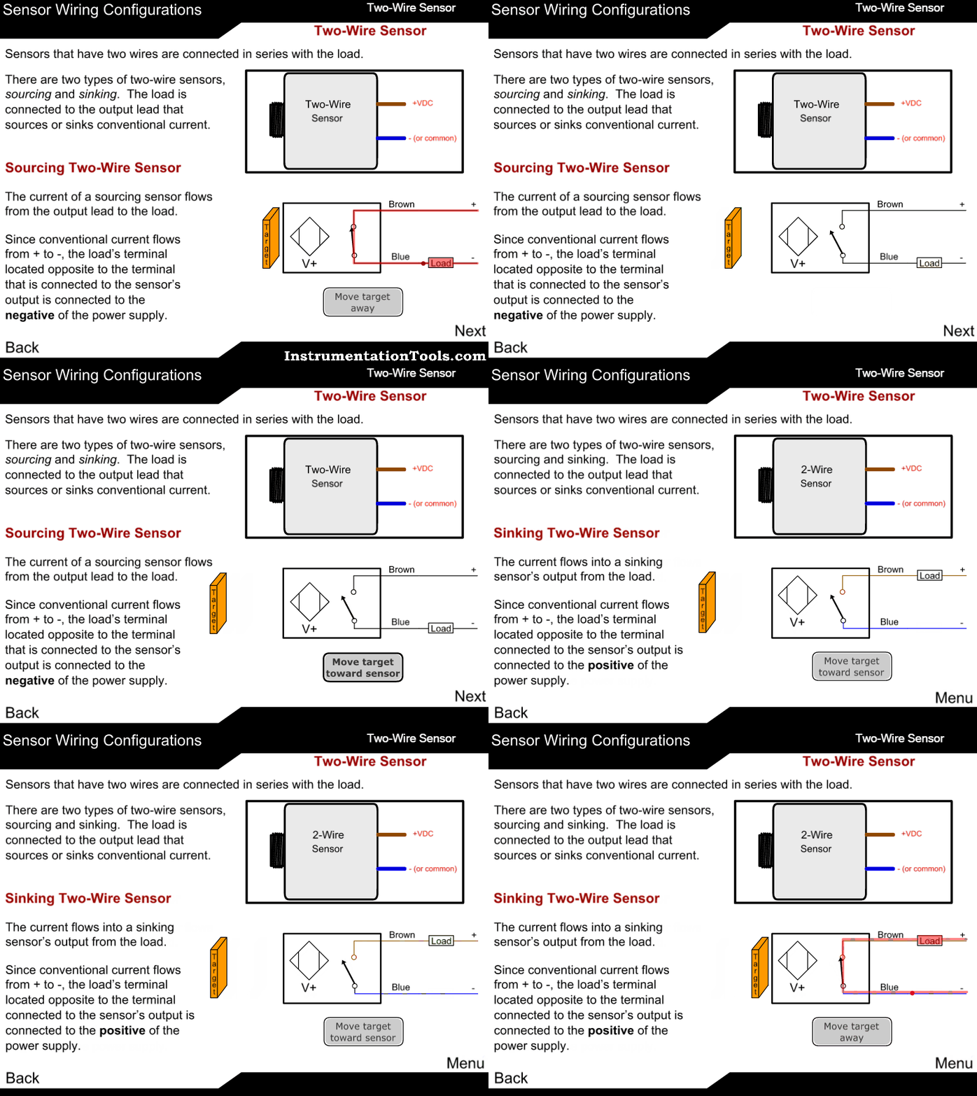
Two-wire devices are designed to wire in series with the load. In a 3-wire configuration, two of the three leads supply power while the third switches the load. Both types can be wired strategically, in series or parallel configurations, to conserve inputs or perform logic.

Two-wire sensors are the easiest devices to wire, but they can hinder the overall system performance. Two-wire sensors require power from the same line they are switching; this, combined with their characteristically higher voltage drop, typically limits the practical number that can be connected to two.

In addition, because each device supplies power to the subsequent devices, response time is equal to the sum of the turn-on times for each device.

Two Wire Sensor

Two Wire Sensor principle

Difference between 2-wire and 3-wire technology

What exactly is the difference between the 4-20 mA output signal in 2- and 3-wire technology? This question is answered best from the viewpoint of the user: An output signal in 2-wire technology means:

  • less wiring required
  • better EMC protection, since interferences can be filtered more easily
  • better protection against wiring errors

The only advantage of 3-wire technology is that higher ohmic loads are possible, i.e., the current loop can also be operated on a measuring instrument of relatively high input impedance.

Conclusion: With the exception of a high ohmic load requirement, 4-20 mA in 2-wire technology offers the user clear advantages- also over other signals, such as 0-10 V

2 wire sensor is basically a loop-powered device without requiring a separate supply voltage (the source voltage is supplied to the destination device) whereas the 3 wire sensor is a self-powered device meaning, you supply source voltage to the sensor and it can drive a 4-20 ma input device directly without the destination device requiring any supply voltage.

Generally, 3 wire devices can supply to larger impedance load compared to 2 wire devices at the same voltage levels.

2 wire devices are easy to connect in circuits with a positive or negative common i.e. you can insert anywhere in a loop whereas 3 wire devices connections are usually fixed.
Don't Miss Our Updates
Be the first to get exclusive content straight to your email.
We promise not to spam you. You can unsubscribe at any time.
Invalid email address
You've successfully subscribed !

Continue Reading

How Modbus is used in Industrial Networks?
Capacitive Level Switch Principle
Switch Types and Common Terminology
Tuning Fork Level Switch Principle
Basics of Pressure switches
Main differences between Sinking and Sourcing Circuits
Share This Article
Facebook Whatsapp Whatsapp LinkedIn Copy Link
Share
3 Comments
  • Isaac Newton says:
    August 9, 2016 at 4:24 pm

    Thanks

    Reply
  • Manuel Rojo says:
    April 24, 2022 at 10:35 pm

    Thank you for your publication explanation on sensor devices. I’m working on the sensor. Input 3 pins and 2 wires output connector which chow positive and negative. 5 volts on it when is hooked up. To the sensor dropped to 2.27 volts can you get me an idea of what could be happening. Thank you in advance

    Reply
  • Salvador Saldivar says:
    July 30, 2022 at 6:26 pm

    Someone pull the two wires from a crash sensor, on a Honda civic, and the two are black, how do I know which one is going on the right or left of the sensor ? Thanks !

    Reply

Leave a Reply Cancel reply

Your email address will not be published. Required fields are marked *

Stay Connected

128.3kFollowersLike
69.1kFollowersFollow
210kSubscribersSubscribe
38kFollowersFollow

Categories

Explore More

Tilt Level Switch Working Principle
Pull Cord Switch Working Principle
Microwave Barrier Level Switch Working Principle
Fire Water Sprinklers Working Principle
Online Simulation
Pull Up and Pull Down Switch Circuits
Rotary Abutment Flow Meters Working Principle and Animation
Hall Effect Sensor Working Principle Animation

Keep Learning

Radar Level Transmitter in Briddle level Measurement

Radar Level Transmitter in Briddle level Measurement

gate-valve-principle-animation

Basics of Gate Valves

Side Mounting Float Switch Working Principle

Side Mounting Float Switch Working Principle

Paddle Wheel Level Switch Principle

Paddle Wheel Level Switch Principle

Pyrometer Principle

Optical Pyrometer Working Principle Animation

Chromatograph Principle

Basics of Chromatograph Operation

Argonite/CO2 Flooding System Master & Slave Cylinder Operation

Tilt Level Switch Working Animation

Learn More

Probability of failure on demand (PFD)

Probability of Failure on Demand (PFD)

What is a Router

What is a Router? How Does a Router Work?

PLC Program

Example PLC Program

What is ELCB

What is ELCB? Principle, Advantages, Disadvantages, Applications

Electronic Devices & Circuits Objective Questions

Electronic Devices & Circuits Quiz – Set 13

Tree (chicken foot) topology

Fieldbus Device Capability

Electrical Cables Interview Questions & Answers

Conductor Size Selection in Distribution Power System

Pressurizer

Pressurizer

Menu

  • About
  • Privacy Policy
  • Copyright

Quick Links

  • Learn PLC
  • Helping Hand
  • Part Time Job

YouTube Subscribe

Follow US
All rights reserved. Reproduction in whole or in part without written permission is prohibited.
Welcome Back!

Sign in to your account

Username or Email Address
Password

Lost your password?