This article will discuss the implementation of a Traffic signal control system that can run in automatic mode and manual mode with push buttons in Siemens PLC. In automatic mode, the system controls the switching On of Green, Yellow, and Red lights alternately with a predetermined time interval duration for each color. In manual mode, control of lighting the lights is carried out individually via buttons and In this mode, it allows the user to adjust the light conditions according to their needs directly.
Program Objective
Traffic Light Sequence:
1. Auto Mode
Mode Setting: Selector Switch position is set to “Auto” mode.
Initial Cycle: When the program is run in automatic mode, the Green light will be on first.
Light Switching Sequence:
- Green light is On for 5 seconds.
- After that, the Yellow light turns on for 3 seconds.
- Next, the Red light turns on for 4 seconds.
Cycle Repetition: After the Red light goes Off, the cycle will return to the beginning with the Green light On for 5 seconds, followed by alternating Yellow and Red lights.
Repeating Process: This color change cycle will continue to repeat automatically as long as “Auto” mode is active, until the “Stop” button is Pressed to Stop the program.
2. Manual Mode
Mode Setting: Change the Selector Switch position to “Manual” mode.
Light Control:
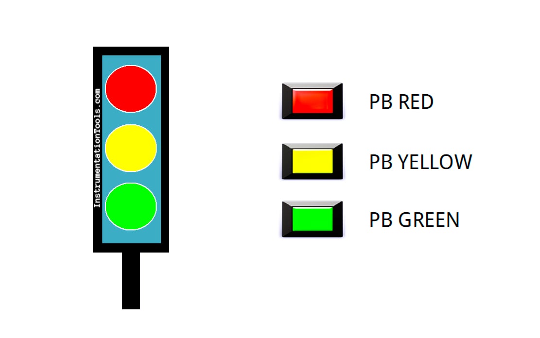
- There are three buttons, each to turn On and Off. The Green, Yellow, and Red lights turn on separately.
- The light will only turn On when the corresponding button is Pressed, allowing full manual control of the system.
Traffic Light using Siemens TIA Portal

Mapping Details
| S.No. | Comment | Input (I) | Output (Q) | Memory Bit | Timer |
|---|---|---|---|---|---|
| 1 | START | I0.0 | |||
| 2 | STOP | I0.1 | |||
| 3 | SELECTOR_SWITCH | I0.2 | |||
| 4 | PB_GREEN | I0.3 | |||
| 5 | PB_YELLOW | I0.4 | |||
| 6 | PB_RED | I0.5 | |||
| 7 | LAMP_GREEN | Q0.0 | |||
| 8 | LAMP_YELLOW | Q0.1 | |||
| 9 | LAMP_RED | Q0.2 | |||
| 10 | TIMER1 | DB1 | |||
| 11 | TIMER2 | DB2 | |||
| 12 | TIMER3 | DB3 | |||
| 13 | SYSTEM_ON | M0.0 | |||
| 14 | IR_GREEN | M0.1 | |||
| 15 | IR_YELLOW | M0.2 | |||
| 16 | IR_RED | M0.3 | |||
| 17 | IR_TIMER1 | M0.4 | |||
| 18 | IR_TIMER2 | M0.5 | |||
| 19 | IR_TIMER3 | M0.6 |
Traffic Signal Control with Push Buttons
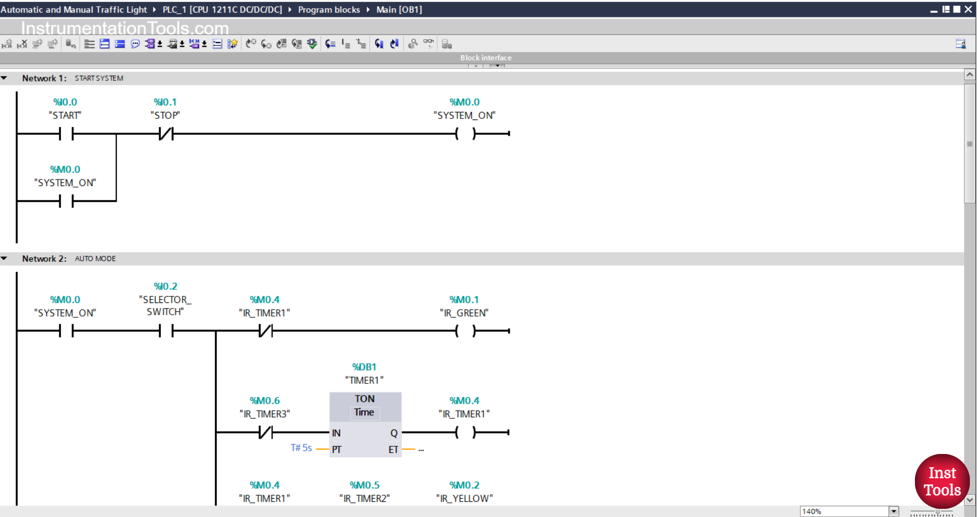
NETWORK 1 (START SYSTEM)
In this network, when the START(I0.0) button is pressed, the memory bit SYSTEM_ON (M0.0) will be in the HIGH state. Because it uses Latching, even though the START (I0.0) button has been released the memory bit SYSTEM_ON (M0.0) will remain in the HIGH state.
The memory bit SYSTEM_ON (M0.00 will be in the LOW state if the STOP (I0.1) button is pressed.
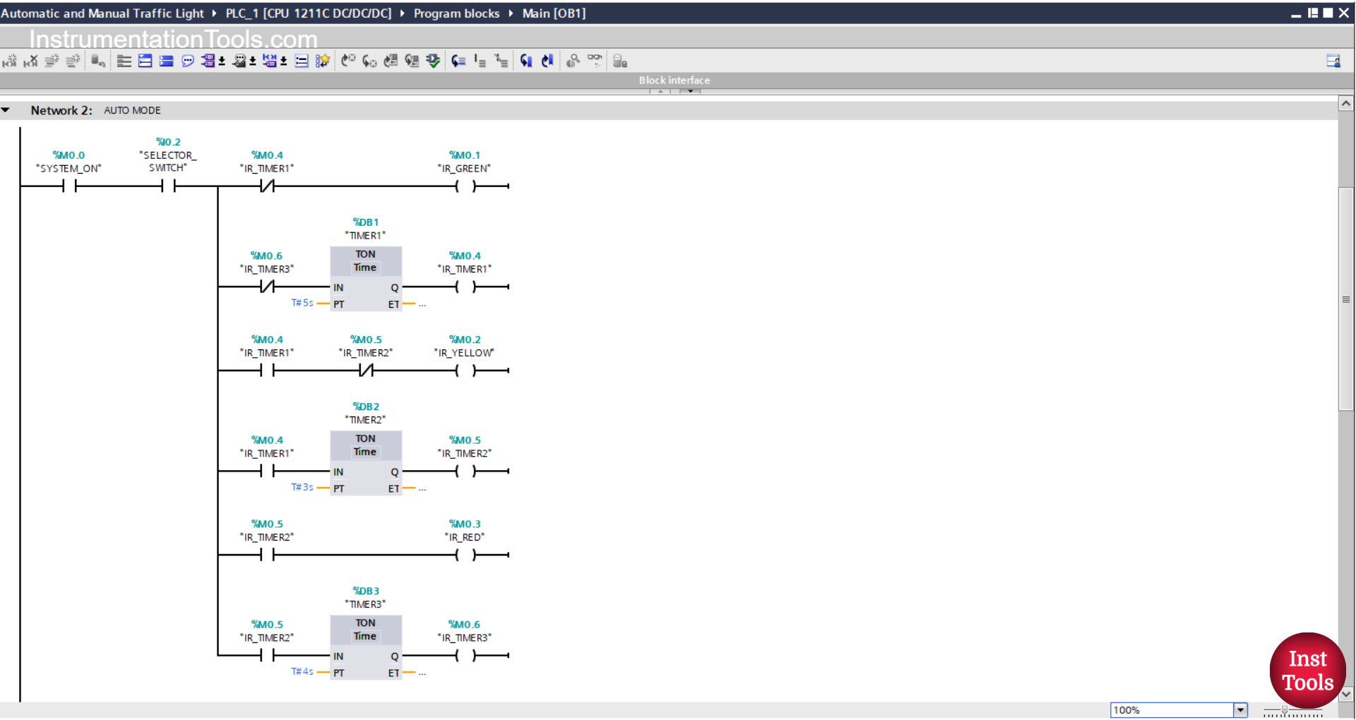
NETWORK 2 (AUTO MODE)
In this Network, the memory bit IR_GREEN (M0.1) will be in the HIGH state when the NO contact of the memory bit SYSTEM_ON (M0.0) and the NO contact of the selector switch SELECTOR_SWITCH (I0.2) are in the HIGH state. Timer TIMER1 (DB1) will Start counting.
The TIMER1 (DB1) timer will count up to 5 seconds, and after it has finished counting, the memory bit IR_GREEN (M0.1) will be in LOW state; the memory bits IR_TIMER1 (M0.4) and IR_YELLOW (M0.2) will be in HIGH state.
Next, Timer TIMER2 (DB2) will start counting up to 3 seconds.
The memory bits IR_TIMER2 (M0.5) and IR_RED (M0.3) will be in the HIGH state, and the memory bit IR_YELLOW (M0.2) will be in the LOW state due to the interlock of the memory bit IR_TIMER2 (M0.5).
The TIMER3 (DB3) timer will start counting up to 4 seconds.
When Timer TIMER3 (DB3) has finished counting, the memory bit IR_TIMER3 (M0.6) will be in the HIGH state.
Timer TIMER1 (DB1) will be reset due to the interlock of memory bit IR_TIMER3 (M0.6).
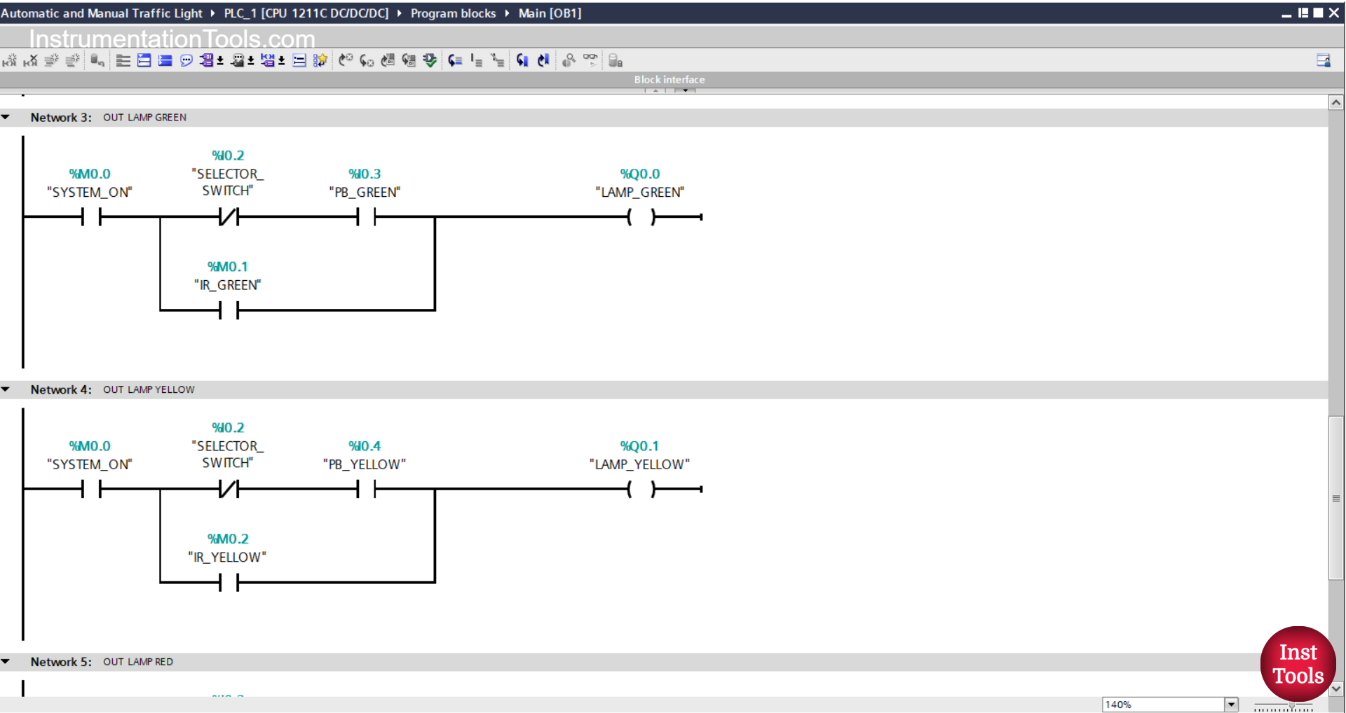
NETWORK 3 (OUT LAMP GREEN)
In this Network, the output LAMP_GREEN (Q0.0) will be ON if the NO contact of the memory bit SYSTEM_ON (M0.0) is in the HIGH state, the NC contact of the selector switch SELECTOR_SWITCH (I0.2) is in the LOW state, and the PB_GREEN (I0.3) button is pressed.
Or, the LAMP_GREEN (Q0.0) output will be ON when the NO contact of the memory bit IR_GREEN (M0.1) is in the HIGH state.
NETWORK 4 (OUT LAMP YELLOW)
In this Network, when the NO contact of the memory bit SYSTEM_ON (M0.0) is in the HIGH state, the NC contact of the selector switch SELECTOR_SWITCH (I0.2) is in the LOW state, and the PB_YELLOW (I0.4) button has been pressed, the output LAMP_YELLOW (Q0.1) will be ON.
Or, the LAMP_YELLOW(Q0.1) output will be ON when the NO contact of the IR_YELLOW(M0.2) bit memory is in the HIGH state.
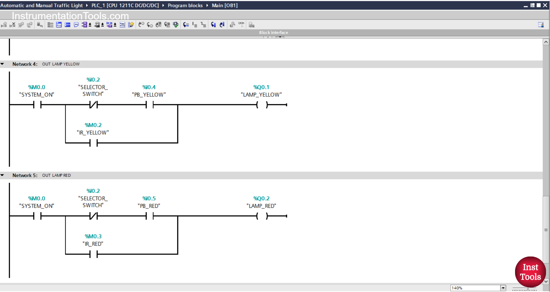
NETWORK 5 (OUT LAMP RED)
In this Network, the LAMP_ RED (Q0.2) output will be ON if the NO contact of the memory bit SYSTEM_ON (M0.0) is in the HIGH state, the NC contact of the selector switch SELECTOR_SWITCH (I0.2) is in the LOW state, and the PB_ button RED (I0.5) has been pressed.
Or, the LAMP_ RED (Q0.2) output will be ON when the NO contact of the memory bit IR_RED (M0.3) is in the HIGH state.
Read Next:
- Mitsubishi PLC Counter Tutorial Using GX-Works2
- Siemens PLC Lamp Logic Programming Exercise
- PLC Project: Automatic Parking with Vehicle Counter
- Siemens TIA Portal Elevator System with Safety Features
- Mitsubishi PLC Timers with Ladder Diagram Explained