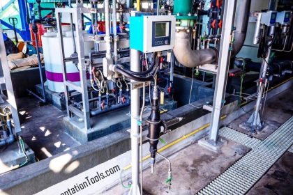
Inst ToolsInst ToolsInst Tools
  • Courses
  • Automation
    • PLC
    • Control System
    • Safety System
    • Communication
    • Fire & Gas System
  • Instrumentation
    • Design
    • Pressure
    • Temperature
    • Flow
    • Level
    • Vibration
    • Analyzer
    • Control Valve
    • Switch
    • Calibration
    • Erection & Commissioning
  • Interview
    • Instrumentation
    • Electrical
    • Electronics
    • Practical
  • Q&A
    • Instrumentation
    • Control System
    • Electrical
    • Electronics
    • Analog Electronics
    • Digital Electronics
    • Power Electronics
    • Microprocessor
  • Request
Search
  • Books
  • Software
  • Projects
  • Process
  • Tools
  • Basics
  • Formula
  • Power Plant
  • Root Cause Analysis
  • Electrical Basics
  • Animation
  • Standards
  • 4-20 mA Course
  • Siemens PLC Course
Reading: Total Organic Carbon Analyzer Principle
Share
Font ResizerAa
Inst ToolsInst Tools
Font ResizerAa
  • Courses
  • Design
  • PLC
  • Interview
  • Control System
Search
  • Courses
  • Automation
    • PLC
    • Control System
    • Safety System
    • Communication
    • Fire & Gas System
  • Instrumentation
    • Design
    • Pressure
    • Temperature
    • Flow
    • Level
    • Vibration
    • Analyzer
    • Control Valve
    • Switch
    • Calibration
    • Erection & Commissioning
  • Interview
    • Instrumentation
    • Electrical
    • Electronics
    • Practical
  • Q&A
    • Instrumentation
    • Control System
    • Electrical
    • Electronics
    • Analog Electronics
    • Digital Electronics
    • Power Electronics
    • Microprocessor
  • Request
Follow US
All rights reserved. Reproduction in whole or in part without written permission is prohibited.
Inst Tools > Blog > Analyzers > Total Organic Carbon Analyzer Principle

Total Organic Carbon Analyzer Principle

Last updated: March 5, 2018 3:47 am
Editorial Staff
Analyzers Guest Articles
No Comments
Share
3 Min Read
SHARE

 TOC analyzer

Introduction of organic matter into water system occur only from living organisms and from decaying matter in source water, but also from purification and distribution system’s materials. In pharmaceuticals water distribution system, the organic matter are introduced in the form of endotoxins, microbes and development of biofilms on pipeline walls and biofilm growth so it is necessary to maintain low TOC levels. USP, EP and JP recognize TOC as a required test for purified water and Water for Injection. To make sure there is no cross contamination between products of different drugs, various cleaning procedures are performed.

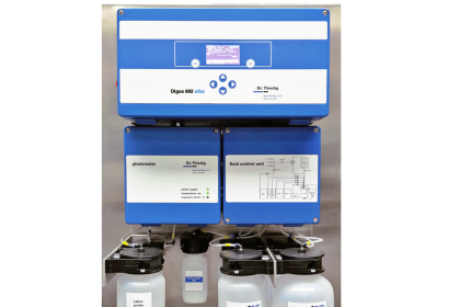
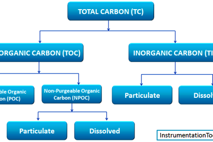
TOC Analyzer measures TOC in pure and ultrapure water based on differential conductivity. This difference in conductivity is used to determine the amount of organic carbon present.

Principle

TOC Analyzer Principle

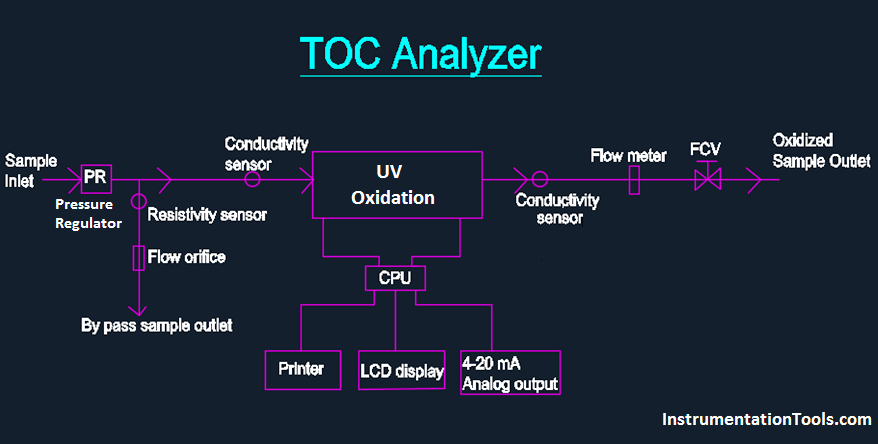
The sample water enters the analyzer and passes through a pressure regulator, which controls sample pressure to downstream components. Then, the sample is splits into two flow paths, where a portion of the flow is directed to the by-pass streamline, where resistivity/ conductivity and temperature are measured via a sensor (a). The other portion flows through another conductivity sensor before passing through the oxidation chamber. The sample is subjected to high intensity UV radiation at 185 nm, effectively oxidizing the sample to CO2.

Then, the oxidized sample passes into another conductivity sensor (b) where the conductivity and temperature are measured again. The difference between the values measured from the (a) and (b) sensors are determined, which is directly proportional to the concentration of organic impurity in the incoming water stream. The water from the (b) sensor is then passed through a flow meter which has a fine flow adjustment and then exits from the outlet which can be rejected or recycled.

The values of TOC, resistivity and temperature are displayed on the LCD screen of the instrument. These values can be printed or sent to a computer via RS 232 serial interface ports and other output can be obtained in the form of 4-20 mA analog output which is further connected to a DCS/PLC system.

Also Read : Basics of Total Organic Carbon Analyzers

Article by :
Muthukrishnan. R
Don't Miss Our Updates
Be the first to get exclusive content straight to your email.
We promise not to spam you. You can unsubscribe at any time.
Invalid email address
You've successfully subscribed !

Continue Reading

pH Analyzer Do’s and Don’ts
3 Phase Motor Control using PLC Ladder Logic
Bently Nevada Vibration Probes Functional Testing
Inhouse Moisture separator for Pneumatic Systems
Absorption Type Optical Analyzer
Capacitance Level Switch Calibration
Share This Article
Facebook Whatsapp Whatsapp LinkedIn Copy Link
Share
Leave a Comment

Leave a Reply Cancel reply

Your email address will not be published. Required fields are marked *

Stay Connected

128.3kFollowersLike
69.1kFollowersFollow
210kSubscribersSubscribe
38kFollowersFollow

Categories

Explore More

Silica Analyzer Problems and Troubleshooting Tips
Chlorine dioxide Analyzer Principle
Top 100 Analytical Instrumentation Engineering Projects
H & B Gas Analyzer Principle and Calibration Procedure
pH Transmitter Problem
Accelerometer Vibration Probe Principle
NDIR Analyzer Filter Cells
pH measurement

Keep Learning

Specific-Conductance-Calibration-Procedure

Specific Conductance Calibration Procedure

Total Organic Carbon Analyzer Working Principle

TOC Analyzer Working Principle

pH Analyzer Calibration and Troubleshooting

Troubleshooting pH Analyzer Common Problems

Chromatograph Principle

Basics of Chromatograph Operation

Displacer Level Transmitter weight calibration

Displacer Level Transmitter Dry Calibration with Weights

PLC Program for Sequential Motor Control

PLC Program for Sequential Motor Control

process gas chromatographs

Multi Column Gas Chromatograph

Circular Chart Recorder Calibration Procedure

Circular Chart Recorder Calibration Procedure

Learn More

Determine the statuses of all lamps and relay coils in the circuit

Determine the Status of Lamps and Relays in the Circuit ?

Instrumentation Design Details

I&C Engineer Roles & Responsibilities – Instrumentation Design

Omron PLC painting program

Product Painting PLC Program using Omron CX-Programmer

Gas Detectors Calibration

Calibration of Gas Detectors

Pressure and Temperature Gauges

Pressure and Temperature Gauges

Control Valve Cv Formula

Control Valve Cv calculation

corroded tank

Cathodic Protection – Sacrificial Anodic and Impressed Current

Power Electronics Objective Questions

Single-Phase Full Wave AC-DC Converter Objective Questions

Menu

  • About
  • Privacy Policy
  • Copyright

Quick Links

  • Learn PLC
  • Helping Hand
  • Part Time Job

YouTube Subscribe

Follow US
All rights reserved. Reproduction in whole or in part without written permission is prohibited.
Welcome Back!

Sign in to your account

Username or Email Address
Password

Lost your password?