Inst ToolsInst ToolsInst Tools
  • Courses
  • Automation
    • PLC
    • Control System
    • Safety System
    • Communication
    • Fire & Gas System
  • Instrumentation
    • Design
    • Pressure
    • Temperature
    • Flow
    • Level
    • Vibration
    • Analyzer
    • Control Valve
    • Switch
    • Calibration
    • Erection & Commissioning
  • Interview
    • Instrumentation
    • Electrical
    • Electronics
    • Practical
  • Q&A
    • Instrumentation
    • Control System
    • Electrical
    • Electronics
    • Analog Electronics
    • Digital Electronics
    • Power Electronics
    • Microprocessor
  • Request
Search
  • Books
  • Software
  • Projects
  • Process
  • Tools
  • Basics
  • Formula
  • Power Plant
  • Root Cause Analysis
  • Electrical Basics
  • Animation
  • Standards
  • 4-20 mA Course
  • Siemens PLC Course
Reading: Time Response of Second Order Systems – I
Share
Notification Show More
Font ResizerAa
Inst ToolsInst Tools
Font ResizerAa
  • Courses
  • Design
  • PLC
  • Interview
  • Control System
Search
  • Courses
  • Automation
    • PLC
    • Control System
    • Safety System
    • Communication
    • Fire & Gas System
  • Instrumentation
    • Design
    • Pressure
    • Temperature
    • Flow
    • Level
    • Vibration
    • Analyzer
    • Control Valve
    • Switch
    • Calibration
    • Erection & Commissioning
  • Interview
    • Instrumentation
    • Electrical
    • Electronics
    • Practical
  • Q&A
    • Instrumentation
    • Control System
    • Electrical
    • Electronics
    • Analog Electronics
    • Digital Electronics
    • Power Electronics
    • Microprocessor
  • Request
Follow US
All rights reserved. Reproduction in whole or in part without written permission is prohibited.
Inst Tools > Blog > Multiple Choice Questions > Time Response of Second Order Systems – I

Time Response of Second Order Systems – I

Last updated: November 27, 2021 5:41 pm
Editorial Staff
Multiple Choice Questions
No Comments
Share
5 Min Read
SHARE

Time Response of Second Order Systems – I

1. Which of the following transfer function will have the greatest maximum overshoot?

a) 9/(s2+2s+9)
b) 16/(s2+2s+16)
c) 25/(s2+2s+25)
d) 36/(s2+2s+36)

Answer: d

Explanation: Comparing the characteristic equation with the standard equation the value of the damping factor is calculated and the value for the option d is minimum hence the system will have the maximum overshoot .

2. A system generated by

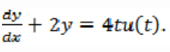
The ramp component in the forced response will be:

a) t u(t)
b) 2t u(t)
c) 3t u(t)
d) 4t u(t)

Answer: b

Explanation:

Laplace transforming
sY(s) + 2Y(s)=4/s2
Taking the inverse Laplace transform the forced term is 2t u(t).

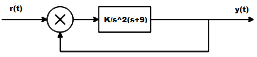
3. The system in originally critically damped if the gain is doubled the system will be :

a) Remains same
b) Overdamped
c) Under damped
d) Undamped

Answer: c

Explanation: 

hence due to this G lies between 0 and 1.

4. Let c(t) be the unit step response of a system with transfer function K(s+a)/(s+K). If c(0+) = 2 and c(∞) = 10, then the values of a and K are respectively.

a) 2 and 10
b) -2 and 10
c) 10 and 2
d) 2 and -10

Answer: c

Explanation: Applying initial value theorem which state that the initial value of the system is at time t =0 and this is used to find the value of K and final value theorem to find the value of a.

5. The damping ratio and peak overshoot are measures of:

a) Relative stability
b) Speed of response
c) Steady state error
d) Absolute stability

Answer: b

Explanation: Speed of response is the speed at which the response takes the final value and this is determined by damping factor which reduces the oscillations and peak overshoot as the peak is less then the speed of response will be more.

6. Find the type and order of the system given below:

a) 2,3
b) 2,2
c) 3,3
d) None of the mentioned

Answer:

Explanation: Type = 2 which is the number of poles at the origin and order is the highest power of the characteristic equation.

7. A system has a complex conjugate root pair of multiplicity two or more in its characteristic equation. The impulse response of the system will be:

a) A sinusoidal oscillation which decays exponentially; the system is therefore stable
b) A sinusoidal oscillation with a time multiplier ; the system is therefore unstable
c) A sinusoidal oscillation which rises exponentially ; the system is therefore unstable
d) A dc term harmonic oscillation the system therefore becomes limiting stable

Answer: c

Explanation: Poles are the roots of the denominator of the transfer function and on imaginary axis makes the system stable but multiple poles makes the system unstable.

8. The forward path transfer function is given by G(s) = 2/s(s+3). Obtain an expression for unit step response of the system.

a) 1+2e-t+e-2t
b) 1+e-t-2e-2t
c) 1-e-t+2e-2t
d) 1-2e-t+e+2t

Answer: d

Explanation: C(s)/R(s) = s/(s2+3s+2)
C(s) = 1/s-2/s+1+1/s+2
c(t) = 1-2e-t+e+2t.

9. Find the initial and final values of the following function:
F(s) = 12(s+1)/s(s+2)^2(s+3)

a) 1,∞
b) 0,∞
c) ∞,1
d) 0,1

Answer: d

Explanation: Using final and initial values theorem directly to find initial and final values but keeping in mind that final value theorem is applicable for stable systems only.

10. The step response of the system is c(t) = 10+8e-t-4/8e-2t . The gain in time constant form of transfer function will be:

a) -7
b) 7
c) 7.5
d) -7.5

Answer: d

Explanation: Differentiating the equation and getting the impulse response and then taking the inverse Laplace transform and converting the form into time constant form we get K = -7.5.

Don't Miss Our Updates
Be the first to get exclusive content straight to your email.
We promise not to spam you. You can unsubscribe at any time.
Invalid email address
You've successfully subscribed !

Continue Reading

Liquid Chromatograph- Mass Spectrometer
Silica Analyzer Questions & Answers
The Design Problem
The Z-Transform
Feedback Compensation
Analyzers Based on Gas Density Questions & Answers
Share This Article
Facebook Whatsapp Whatsapp LinkedIn Copy Link
Share
Leave a Comment

Leave a Reply Cancel reply

Your email address will not be published. Required fields are marked *

Stay Connected

128.3kFollowersLike
69.1kFollowersFollow
210kSubscribersSubscribe
38kFollowersFollow

Categories

Explore More

pH Meters Questions & Answers
Controller Components – Part 1 Objective Questions
Logic Families Questions and Answers
Fuzzy Logic Control
Performance Indices
Block diagram Algebra Objective Questions
Stability of Nonlinear System
Signal Reconstruction

Keep Learning

Radiochemical Questions and Answers

Liquid Scintillation Counters Questions & Answers

Frequency Response MCQ

Experimentation of Transfer Function

Ion Spectrometers Questions & Answers

Auger Electron Spectroscopy

pH Analyzers Questions and Answers

Combination Electrode Questions & Answers

AC Circuits Multiple Choice Questions

Radiochemical Questions and Answers

Radiation Detectors Questions & Answers

Mass Spectrometer Questions and Answers

Magnetic Deflection Mass Spectrometer Questions & Answers

Chromatography Questions & Answers

High Pressure Liquid Chromatography Questions & Answers

Learn More

Imbibition Water Flow Control System

Imbibition Water Flow Control System – Sugar Factory

Displacement Transducers Objective Questions

Displacement Transducers Objective Questions

Electrical Symbols

Electrical Symbols

Fieldbus Control Loop

Foundation Fieldbus Communication Management

Electrical Machines Questions and Answers

Transformer as a Magnetically Coupled Circuit

Machine Tool and Coolant Control PLC Ladder Logic

Machine Tool and Coolant Control: PLC Ladder Logic Design

Profibus network

How Profibus Communication Works

PLC Ladder Program for Automatic Car Wash

PLC Ladder Program for Automatic Car Wash using Siemens TIA Portal

Menu

  • About
  • Privacy Policy
  • Copyright

Quick Links

  • Learn PLC
  • Helping Hand
  • Part Time Job

YouTube Subscribe

Follow US
All rights reserved. Reproduction in whole or in part without written permission is prohibited.
Welcome Back!

Sign in to your account

Username or Email Address
Password

Lost your password?