Thermistors
Thermistors are temperature sensitive semiconductors that exhibit a large change in resistance over a relatively small range of temperature. There are two main types of thermistors, positive temperature coefficient (PTC) and negative temperature coefficient (NTC). NTC thermistors exhibit the characteristic of resistance falling with increasing temperature. These are most commonly used for temperature measurement.
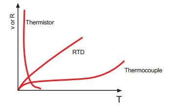
A thermistor is similar to an RTD, but a semiconductor material is used instead of a metal. A thermistor is a solid state device and has larger sensitivity than does an RTD. Unlike RTD’s, the temperature-resistance characteristic of a thermistor is non-linear, and cannot be characterized by a single coefficient. Furthermore, unlike RTDs, the resistance of a thermistor decreases with increasing temperature.
Thermistors cannot be used to measure high temperatures compared to RTDs. In fact, the maximum temperature of operation is sometimes only 100 or 200°C.
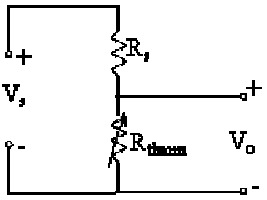
Manufacturers commonly provide resistance-temperature data in curves, tables or polynomial expressions. Linearizing the resistance-temperature correlation may be accomplished with analog circuitry, or by the application of mathematics using digital computation. A typical thermistor circuit is shown below.
From the circuit diagram, it is clear that this is a simple voltage divider. Rs is some fixed (supply) resistor. Rs and the supply voltage, Vs, can be adjusted to obtain the desired range of output voltage Vo for a given range of temperature.
Advantages: Large resistance change with temperature, rapid response time, good stability, High resistance eliminates difficulties caused by lead resistance, Low cost and interchangeable
Disadvantages: Non-linear, limited operating temperature range, may be subjected to inaccuracy due to overheating, current source required.
Resistance vs. Temperature Curve
Unlike RTDs and thermocouples, thermistors do not have standards associated with their resistance vs. temperature characteristics or curves. Consequently, there are many different ones to choose from.
Each thermistor material provides a different resistance vs. temperature “curve”. Some materials provide better stability while others have higher resistances so they can be fabricated into larger or smaller thermistors.
Many manufactures list a Beta (B) constant between 2 temperatures (Example: [3 0/50 = 3890). This, along with the resistance at 25°C (77°F) can be used to identity a specific thermistor curve.
Thermistor is a resistance thermometer, similar to a Resistance Temperature Detector (RTD) and is used fortemperature measurement. It consists of a non-metallic resistor that is used as the temperature sensing element.
Thermistor is the short form for ‘Thermal Resistor’. The device consists of a bulk semiconductor device that acts as a resistor with a high and negative temperature co-efficient of resistance, sometimes as high as -6% per degree Celsius rise in temperature. Due to this property of high sensitivity (that is, huge resistance change for a small change in temperature), the thermistor is mainly applicable in precision temperature measurement, temperature control, and temperature compensation, especially in a lower temperature range of -100 degree Celsius to +300 degree Celsius.
Difference between Thermistor and Resistance Temperature Detectors (RTD)
Both devices work on the same principle that a constant current flowing through the resistor, and its changing resistance due to change in temperature, is measured as a voltage drop across it. The main difference is that the electrical resistance of the resistor used in a thermistor varies in a non-linear manner with respect to temperature. The sensing element used in the thermistor is made up of either a ceramic or polymer, while RTD uses pure metals as its sensing element. Another major difference is in its operating range. Due to its high sensitivity, thermistors are used in narrow span measurements and low temperature ranges from -20 degree Celsius to +120 degree Celsius. But RTD’s are used over wide and larger temperature ranges.
Construction
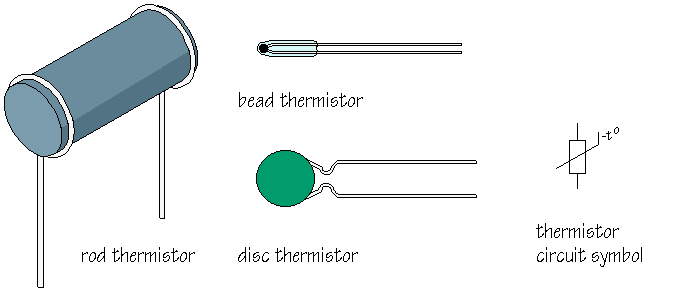
The device is manufactured from materials like sintered mixtures of oxides of metals such as manganese, nickel, cobalt, and iron. Their resistances range from 0.4 ohms to 75 mega-ohms and they may be fabricated in wide variety of shapes and sizes. Smaller thermistors are in the form of beads of diameter from 0.15 millimeters to 1.5 millimeters. Such a bead may be sealed in the tip of solid glass rod to form probe which is easier to mount than bead. Alternatively thermistor may be in the form of disks and washers made by pressing thermistor material under high pressure into flat cylindrical shapes with diameter from 3 millimeters to 25 millimeters. Washers may be stacked and placed in series or parallel to increase power disciplining capability.
Characteristic Curve
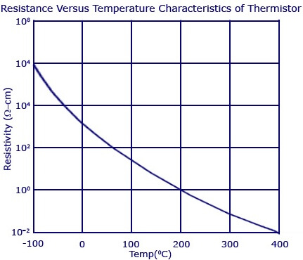
The resistance versus temperature curve is one of the main characteristics that is used in measurement, control and compensation applications using a thermistor. The characteristics graph is shown below. From the characteristics graph of a typical thermistor, we can see that the resistivity changes from 107 to 1 ohm-cm as the temperature changes from -100 degree Celsius to +400 degree Celsius. This high negative temperature coefficient of resistance makes thermistor an ideal temperature transducer.
Thermistor as Temperature Sensor
A thermistor used for the measurement of temperature is shown in the figure below. The thermistor is designed to have a resistance of 2 kilo-ohms at 25 degree Celsius and temperature coefficient of -4% per degree Celsius will bring a reduction of 80 ohms per degree Celsius change in temperature.
The device is connected in series to a battery and a micrometer. A change in temperature causes a change in the resistance if the thermistor and the corresponding micrometer current reading is noted. Usually, the meter is calibrated in terms of temperature with 0.1 degree Celsius resolution. As shown in the figure, a bridge circuit is also used so as to increase the thermistors sensitivity.
Thermistor Types
For studying about the different types of thermistors, it is important to understand the formula which shows the linear relationship between resistance and temperature.
As a 1st order approximation, the change in resistance is equal to the 1st order temperature co-efficient of resistance times the change in temperature.
dR = k.dT
where, dR – Change in Resistance
k – 1st Order Temperature Coefficient of Resistance
dT – Change in Temperature
If the value of temperature coefficient of resistance (k) is positive, an increase in temperature increases the resistance. Such a device can be called a Posistor or Positive Temperature Coefficient Thermistor (PTC). If the value of k is negative, an increase in temperature will decrease the resistance value. Such a device is called a Negative Temperature Coefficient Thermistor (NTC).
Posistor/Positive Temperature Coefficient (PTC) Thermistors
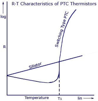
PTC Thermistors that are used in industries are broadly classified into two. The first one is called by the name ‘Silistors’, as to Sensitive Silicon Resistors. Silistors are known to have a positive temperature coefficient of 08% per degree Celsius. If the temperature goes higher than 175 degree Celsius, the device jumps to a negative temperature coefficient region. The other classification of PTC Thermistors is called Switching Type PTC Thermistors. It is made from ceramic type materials and are known to have a very high resistance from a small change in temperature. Dopant’s are also added to the material so that they show a semi-conductive behavior as well. The device is known to have a transition or “Curie” temperature. Until the device reaches that particular point, it shows a negative temperature co-efficient pattern in its resistance-temperature characteristics. After this point, it starts to show an increasing positive temperature coefficient of resistance. At this point, the resistance also begins to develop. The main difference in the temperature-resistance curve between a silistor and switching PTC Thermistor is shown below.
Applications
- The device is famous for its application as a circuit protecting device, such as a fuse. The flow of current through the device causes a heat to build up due to its resistive property. Thus, if excessive current flows through the device, the device begins to heat up accordingly and thus increases its resistance. This increase in resistance again builds up more heat. This creates such an effect that develops more resistance in the device, and limits the amount of voltage and current in the device.
- Another major application is as a timer in degaussing coil circuit of CRT monitors. When a CRT monitor is turned on, an initial current reaches the PTC thermistor and degaussing coil. The PTC thermistor will be of large size and thus, the resistance of the device increases as the current flows in. This causes the heat to build up and thus the degaussing coil shuts off very fast. The degaussing coil is necessary to decrease the continuous magnetic field in a smooth manner. This help can be provided only by the PTC thermistor.
Negative Temperature Coefficient (NTC) Thermistors
NTC Thermistors that are used in industries are broadly classified into two. Thus classification is based on the method by which the electrodes are placed on the ceramic body. This main category could be further divided depending on the different types of geometries, shapes and processing methods. One of the main categories that is most commonly used in the industries is the bead type thermistors. According to the shape and manufacturing methods, bead thermistors can be again classified into Bare Beads, Glass Coated Beads, Ruggedized Beads, and Bead in glass Enclosures and many more.
Another group of NTC Thermistors is the ones with metalized surface contacts. These thermistors can be mounted using spring contacts or by surface mounting.
Applications
- NTC thermistors are used for temperature measurements (usually in a narrow span and low temperature ranges).
- The device can be used to limit the sudden over current that flows in supply circuits. The device is known to have a very high value of resistance in the beginning. The resistance gradually decreases by the heating up of the device. As the resistance decreases, the usual operation of the circuit is restored and the high current flows through it without damaging other parts of the circuit.
- This device is used to measure the temperature of incubators.
- NTC thermistors are used to measure and monitor batteries while they are kept for charging.
- They are used to know the temperature of oil and coolant used inside automotive engines. This information is sent back to the driver through indirect ways.
PTC & NTC Thermistors Comparison
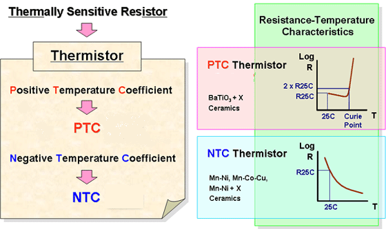
Thermistor,abbreviated for THERMally sensitive resiSTOR.
PTC, abbreviated for Positive Temperature Coefficient.
NTC, abbreviated for Negative Temperature Coefficient.
PTC thermistor resistance increases with temperature rising.
NTC thermistor resistance decreases with temperature rising.
PTC Thermistor major material BaTio3, NTC thermistor major material is Mn, Ni, Cu.
PTC thermistor is mainly applied in over-current overload and short circuit protection, telecom protection, lighting soft switching time delay, motor starting, temperature sensing & protection, self-regulation heating,etc.
NTC thermistor is mainly applied in inrush current suppressing limiting, temperature sensing measurement, temperature compensation, temperature control, etc.
Also Read: RTD Working Principle







This artical so helpful for us ..thank you for sharing
Learning is important learning