The transmitters will accept a variety of RTD configurations, including 2-wire, 3-wire, 4-wire. If the transmitter is mounted remotely from a 3-wire or 4-wire RTD, it will operate within specifications, without recalibration, for lead wire resistances of up to 60 ohms per lead (equivalent to 6,000 feet of 20 AWG wire).
In this case, the leads between the RTD and 4-20ma transmitter should be shielded. If using only two leads, both RTD leads are in series with the sensor element, so significant errors can occur if the lead lengths exceed three feet of 20 AWG wire (approximately 0.05 °C/ft). For longer runs, attach a third or fourth lead as described above.
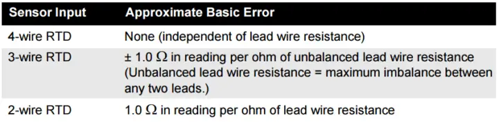
When using a 4-wire RTD, the effect of lead resistance is eliminated and has no impact on accuracy. However, a 3-wire sensor will not fully cancel lead resistance error because it cannot compensate for imbalances in resistance between the lead wires.
Using the same type of wire on all three lead wires will make a 3-wire RTD installation as accurate as possible. A 2-wire sensor will produce the largest error because it directly adds the lead wire resistance to the sensor resistance. For 2- and 3-wire RTDs, an additional lead wire resistance error is induced with ambient temperature variations.
The table and the examples shown below help quantify these errors.
Consider a RTD with the following parameters mentioned below. Calculate Resistance error or final temperature reading error in the transmitter with 2-wire, 3-wire and 4-wire configurations.
Given Data:
Total cable length: 150 m
Imbalance of the lead wires at 20 °C: 1.5 Ω
Resistance/length (18 AWG Cu): 0.025 Ω/m °C
Temperature coefficient of Cu (αCu): 0.039 Ω/Ω °C
Temperature coefficient of Pt(αPt): 0.00385 Ω/Ω °C
Change in Ambient Temperature (∆Tamb): 25 °C
RTD Resistance at 0 °C (Ro): 100 Ω (for Pt 100 RTD)
No lead wire resistance effect
Reference : Rosemount Temp Manual
Learn an example PLC program to control a pump based on level sensors using ladder…
In the PLC timer application for security camera recording, when motion is detected then camera…
In this example, we will learn batch mixing with PLC ladder logic program using timer…
This PLC example on manufacturing line assembly is an intermediate-level PLC program prepared for the…
In this article, you will learn the PLC programming example with pushbutton and motor control…
This article teaches how to convert Boolean logic to PLC programming ladder logic with the…


View Comments
Very very useful data thanq for giving me such a data
Thankyou so much Sir.You are doing a great job. Your efforts are helping thousands of people like me. God bless!
Very very useful
I was having a question. It will be of grate help if someone could help me out.
How are you going to compensate temperature in a RTD??
I have an RTD. Sometime the reading go bad and some time it ok. I measure rtd resistance it ok. And wire not shorted. It if the rtd body touches the metal piping it causes my reading on my transmitter to go bad. I remove the rtd from any metal contact then ok. We have replace the transmitter also same.
Is it possible that the error due to amb. temp. var. of +-25 deg C, for 3-wire RTD, would be +-0.13degC (instead of +-13 deg C)?