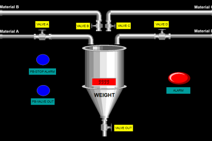
This article will discuss PLC programming to automate the process of monitoring and controlling liquid levels in a Tank Farm. This system will monitor the liquid level continuously, activate the pump to fill or empty the tank, and provide Full or Empty level indicator alarms.
Program Objective
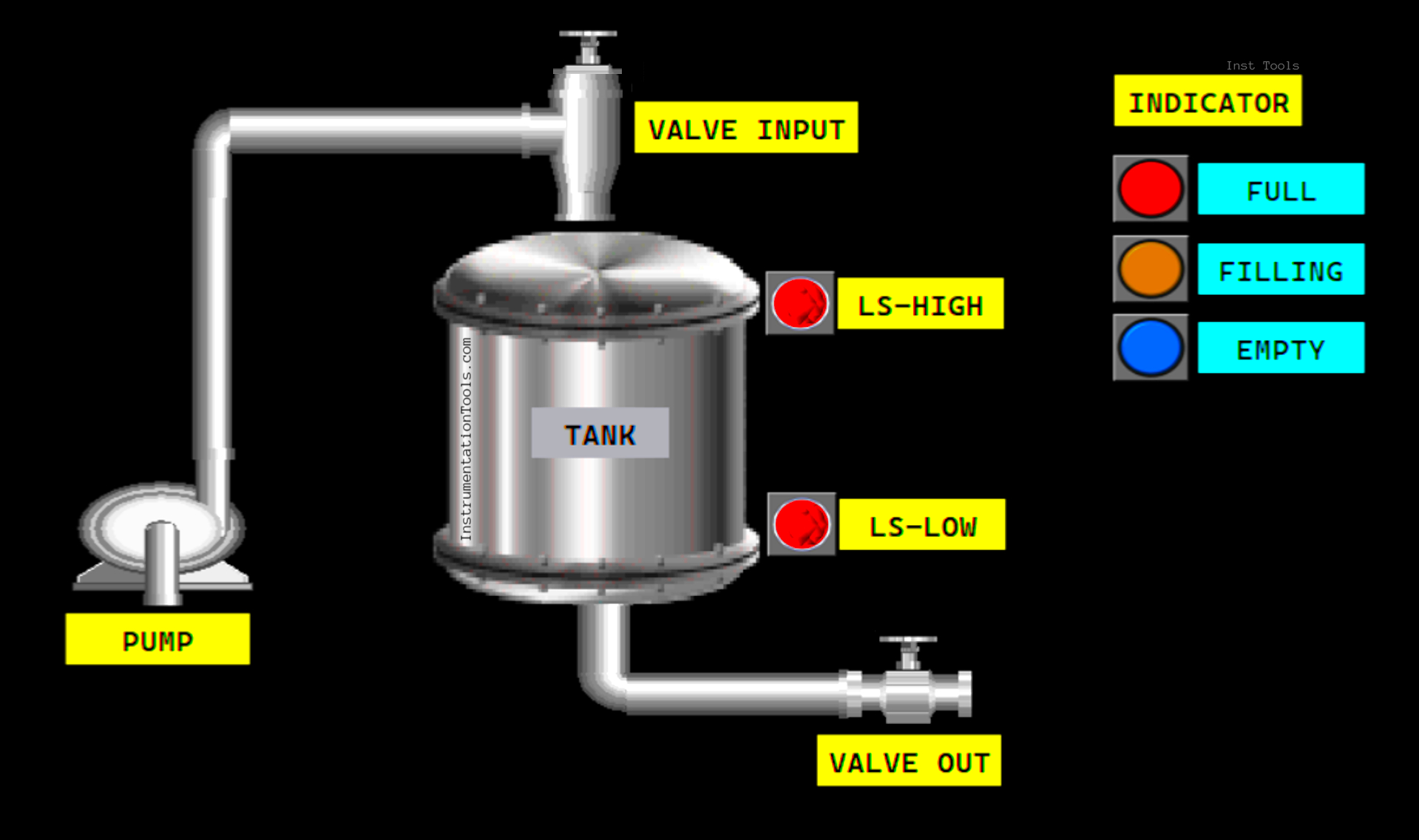
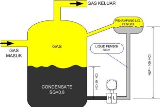
This system has:
- Level Sensor: To measure the liquid level in the tank.
- Pump: To fill liquid into the tank.
- Valve: To control liquid flow.
- Indicator: Indicator light to show system status (Full, Filling, and Empty).
When the system has been started and the liquid content in the tank is below the minimum level, the system will automatically start the filling process.
The liquid Input Valve will open, and 3 seconds later, the Pump will turn ON.
When the liquid content has reached the maximum level limit, the Input Valve will close and the Pump will turn OFF.
This system has a liquid Output Valve and can only be operated manually using a button.
CX-Programmer [OMRON PLC Program]
![Tank Farm Management System CX-Programmer [OMRON]](https://instrumentationtools.com/wp-content/uploads/2025/06/Tank-Farm-Management-System-CX-Programmer-OMRON-scaled.png)
IO Address
The program IO is addressed as follows:
| Comment | Input (I) | Output(Q) | Memory Bits | Timer |
| START | 0.00 | |||
| STOP | 0.01 | |||
| LS_LOW | 0.02 | |||
| LS_HIGH | 0.03 | |||
| VALVE_OUT_OPEN | 0.04 | |||
| VALVE_OUT_CLOSE | 0.05 | |||
| VALVE_INPUT | 100.00 | |||
| PUMP | 100.01 | |||
| VALVE_OUT | 100.02 | |||
| FILLING_INDICATOR | 100.03 | |||
| FULL_INDICATOR | 100.04 | |||
| EMPTY_INDICATOR | 100.05 | |||
| TIMER1 | T0000 | |||
| SYSTEM_ON | W0.00 | |||
| CUTOFF_VALVE_INPUT | W0.01 |
Tank Farm Management System
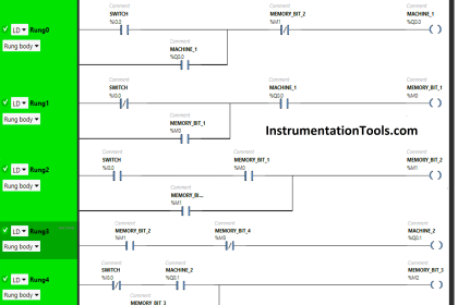
RUNG 0 (SYSTEM_ON)
In this Rung, when the START (0.00) button is Pressed, the memory bit SYSTEM_ON (W0.00) will be in the HIGH state. Because it uses the KEEP(011) instruction, the memory bit SYSTEM_ON (W0.00) will remain in the HIGH state even though the START (0.00) button has been Released.
The memory bit SYSTEM_ON (W0.00) will be in the LOW state if the STOP (0.01) button is Pressed.
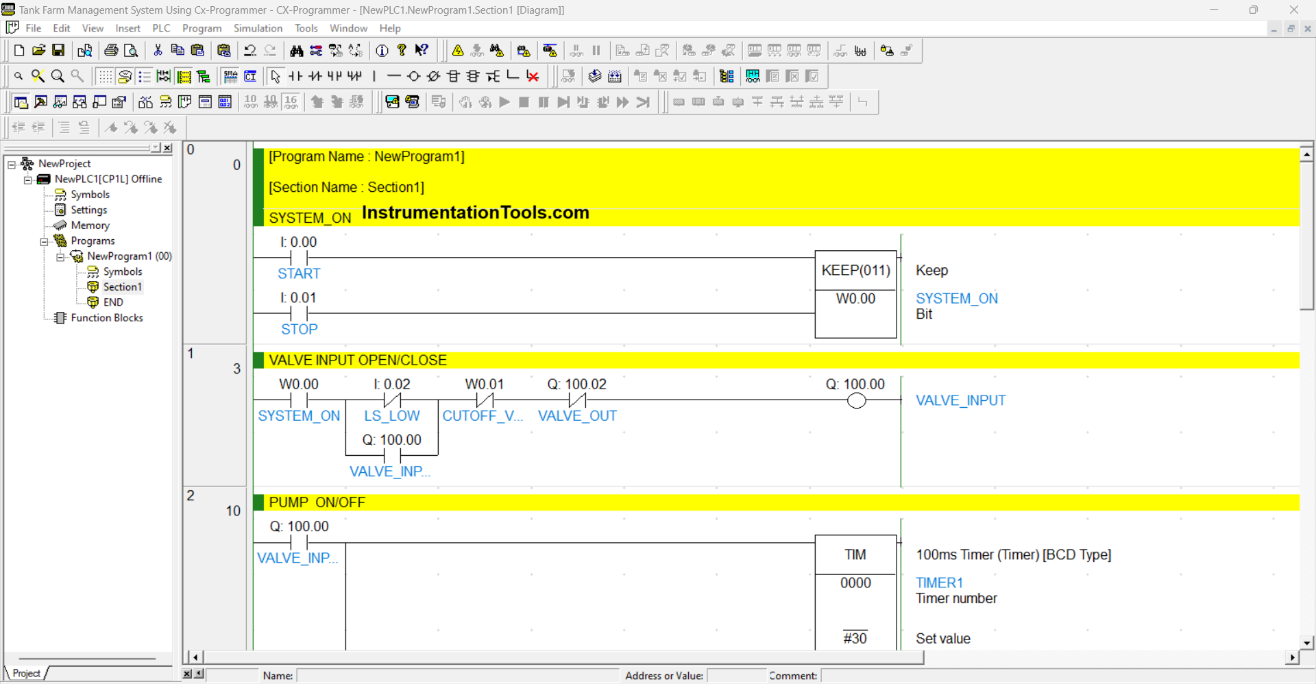
RUNG 1 (VALVE INPUT OPEN/CLOSE)
In this Rung, if the NO contact of memory bit SYSTEM_ON (W0.00) is in the HIGH state and Sensor LS_LOW (0.02) is in the LOW state, then the output VALVE_INPUT (100.00) will be OPEN.
The VALVE_INPUT (100.00) output will be CLOSED if the NC contact of CUTOFF_VALVE_INPUT (W0.01) or VALVE_OUT (100.02) is in the HIGH state.
RUNG 2 (PUMP ON/OFF)
In this Rung, if the NO contact of VALVE_INPUT (100.00) is in the HIGH state, then Timer TIMER1 (T0000) will Start counting up to “3” seconds. When the NO contact of TIMER1 (T0000) is in the HIGH state, the PUMP (100.01) output will be ON.
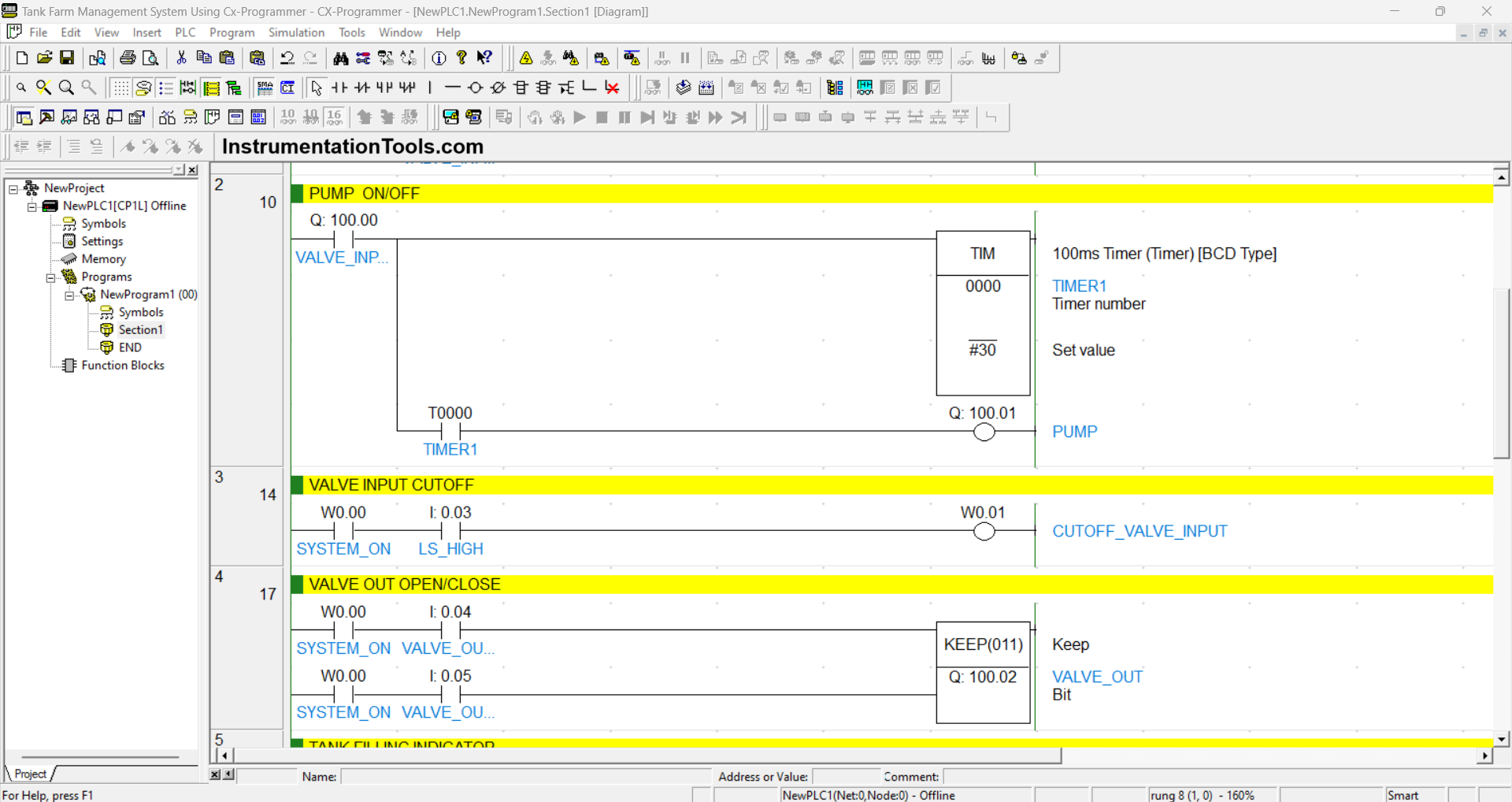
RUNG 3 (VALVE INPUT CUTOFF)
When the NO contact of memory bit SYSTEM_ON (W0.00) and Sensor LS_HIGH (0.03) are in the HIGH state, then the memory bit CUTOFF_VALVE_INPUT (W0.01) will be in the HIGH state.
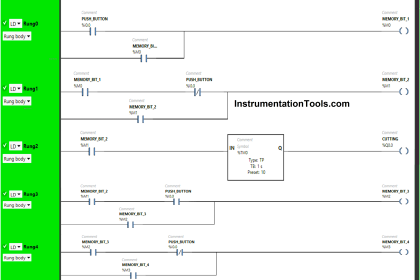
RUNG 4 (VALVE OUT OPEN/CLOSE)
When the NO contact of memory bit SYSTEM_ON (W0.00) in the HIGH state and the VALVE_OUT_OPEN (0.04) button is Pressed, the VALVE_OUT (100.02) output will become OPEN. Because it uses the KEEP(011) instruction, the VALVE_OUT (100.02) output will remain in the OPEN state even though the VALVE_OUT_OPEN (0.04) button has been Released.
And when the VALVE_OUT_CLOSE (0.05) button is Pressed, the VALVE_OUT (100.02) output will become CLOSE.
RUNG 5 (TANK FILLING INDICATOR)
In this Rung, when the NO contact of PUMP (100.01) is in the HIGH state, the FILLING_INDICATOR (100.03) output will be ON.
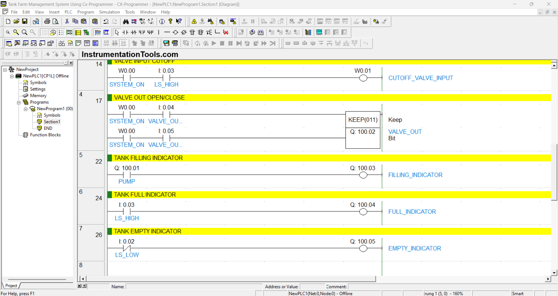
RUNG 6 (TANK FULL INDICATOR)
In this Rung, when the NO contact of Sensor LS_HIGH (0.03) is in the HIGH state, the FULL_INDICATOR (100.04) output will be ON.
RUNG 7 (TANK EMPTY INDICATOR)
In this Rung, when the NC contact of Sensor LS_LOW (0.02) is in the LOW state, the EMPTY_INDICATOR (100.05) output will be ON.
Read Next:
- Omron PLC for Product Painting System
- Automation in Farming & Agriculture
- Siemens LOGO PLC Programming Course
- Purpose of the Marshalling Cabinet
- How to Download GX Works Software?


great explanation