This article discusses the STAR-DELTA Auto and manual system using the XG-5000 Software. This article can be used as a learning medium for students or beginner PLC programmers.
STAR-DELTA Auto And Manual Program
This PLC program has 4 buttons and 1 Selector Switch, the START (P0000) button is used to Turn ON the system, the STOP (P0001) button is used to Turn OFF the system, the STAR_BUTTON (P0003) button is used to Turn ON OUT_STAR (P0040) Output, and the DELTA_BUTTON (P0004) button is used to Turn ON Output OUT_DELTA (P0041).
Selector Switch MODE_BUTTON (P0002) is used to select the system in Auto or Manual mode.
When the START (P0000) button is pressed, the system will Run in MANUAL Mode.
In manual mode, if the STAR_BUTTON (P0003) button is Pressed, the Output OUT_STAR (P0040) will be ON and when DELTA_BUTTON (P0004) button is Pressed, the OUTPUT OUT_DELTA (P0041) will be ON.
When Selector Switch MODE_BUTTON (P0002) is changed to AUTO mode, the Output OUT_STAR (P0040) will be ON for 5 seconds then OFF and the Output OUT_DELTA (P0041) will be ON.
The system will turn OFF if the STOP (P0001) button is Pressed.
PLC IO Details:
| Comment | Inputs (I) | Outputs (Q) | Memory Bits | Timers |
| START | P0000 | |||
| STOP | P0001 | |||
| MODE_BUTTON | P0002 | |||
| STAR_BUTTON | P0003 | |||
| DELTA_BUTTON | P0004 | |||
| OUT_STAR | P0040 | |||
| OUT_DELTA | P0041 | |||
| SYSTEM_ON | M0000 | |||
| MANUAL | M0001 | |||
| AUTO | M0002 | |||
| STAR_MANUAL | M0003 | |||
| DELTA_MANUAL | M0005 | |||
| STAR_AUTO | M0006 | |||
| DELTA_AUTO | M0007 | |||
| TIMER_AUTO | T000 |
XG5000 PLC Programming
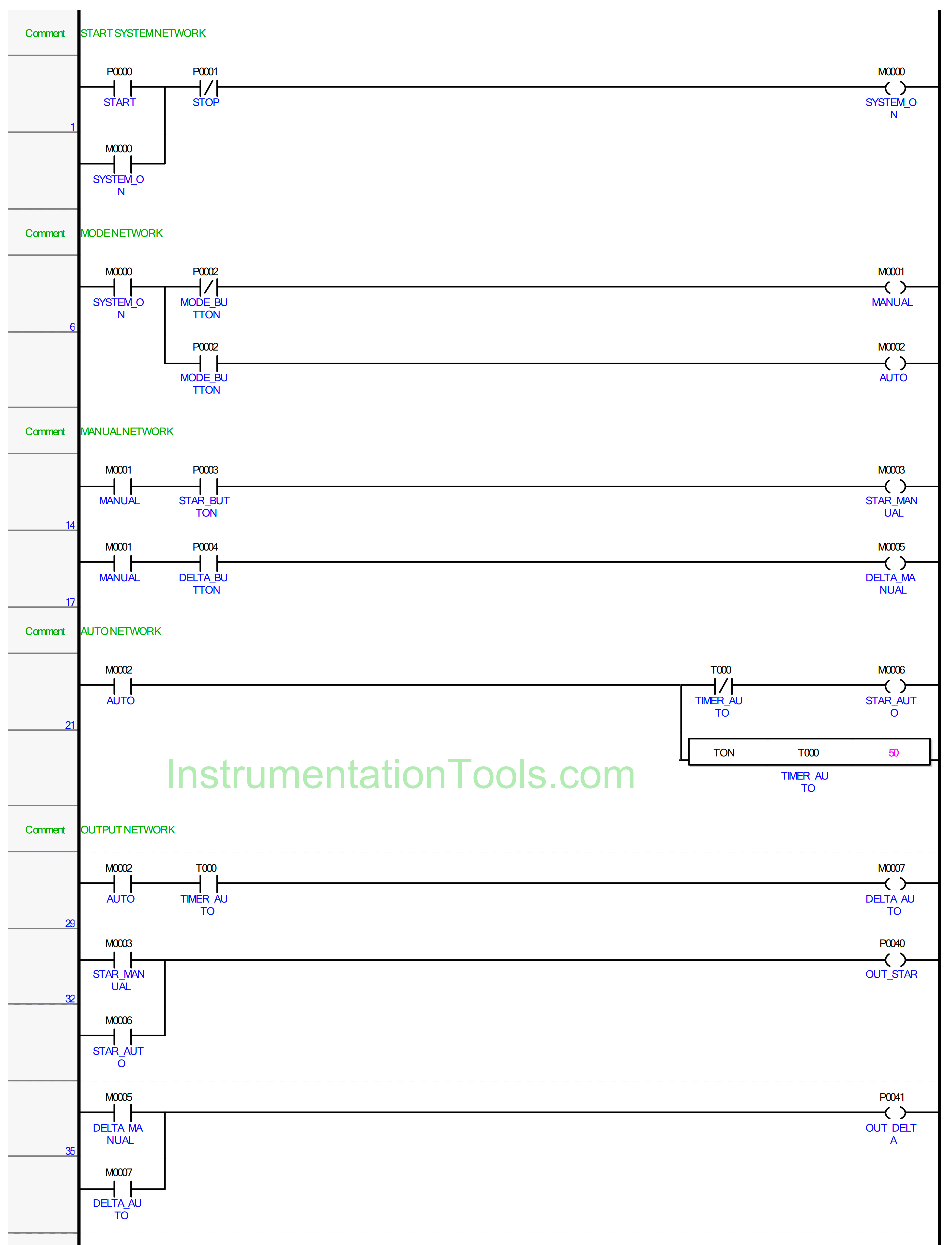
NETWORK 1
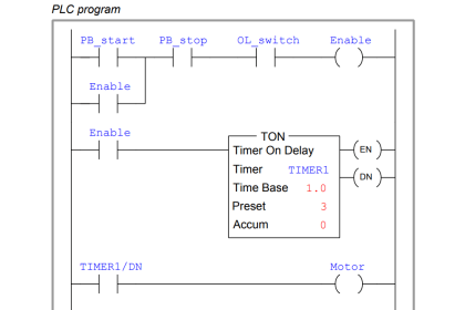
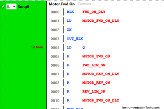
In this Rung, when the START (P0000) button is Pressed, the memory bit SYSTEM_ON (M0000) will become a HIGH state. Because it uses Latching, the memory bit SYSTEM_ON (M0000) remains in the HIGH state even though the START (P0000) button is Released.
The memory bit SYSTEM_ON (M0000) will change to LOW state if the STOP (P0001) button is Pressed.
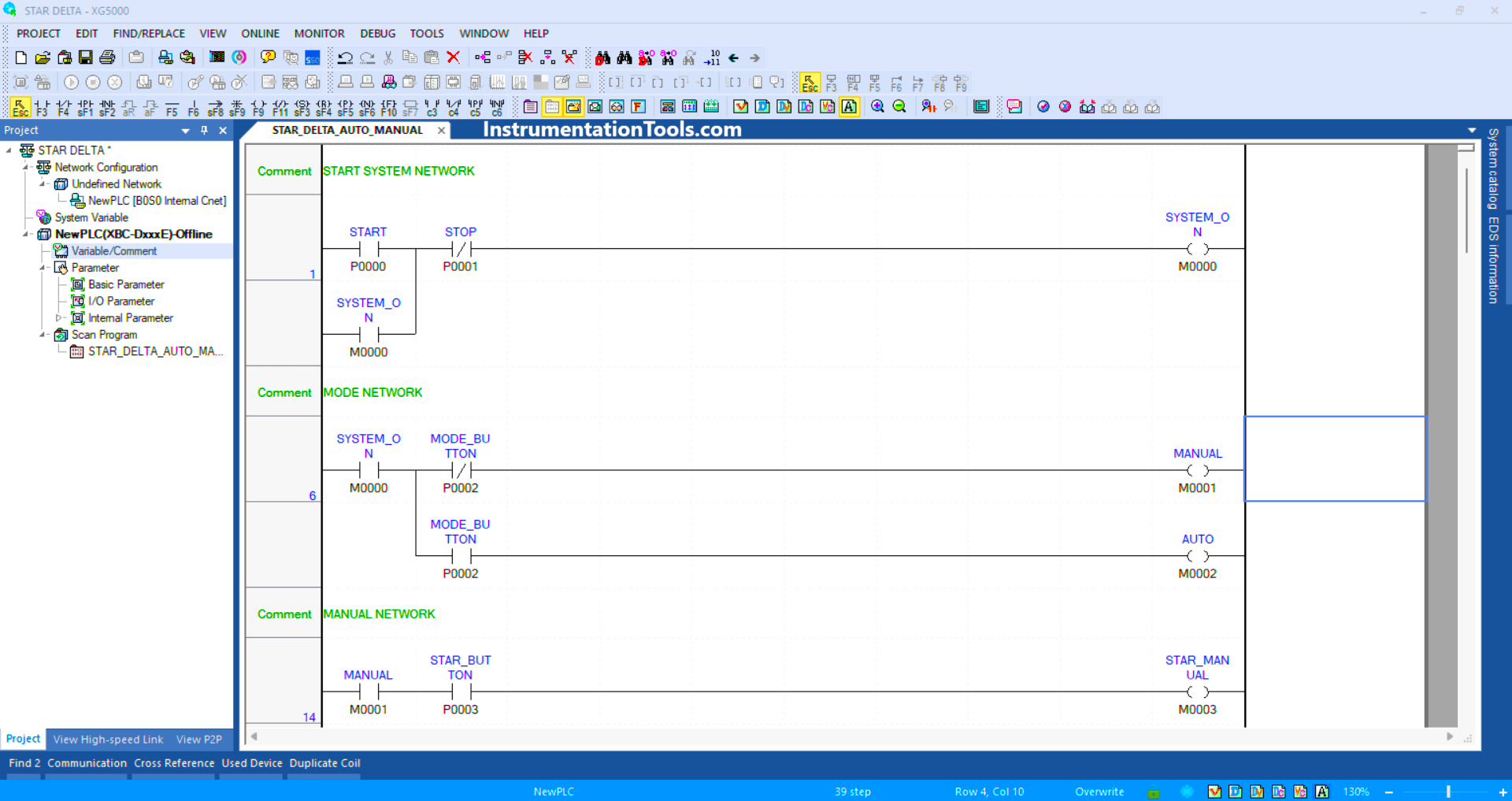
NETWORKS 6
When the NO contact of memory bit SYSTEM_ON (M0000) in the HIGH state and the NC of Selector Switch MODE_BUTTON (P0002) in the LOW state, the memory bit MANUAL (M0001) will be in the HIGH state.
The memory bit AUTO (M0002) will be in the HIGH state when the NO contact of memory bit SYSTEM_ON (M0000) is in the HIGH state and the NO contact of Selector Switch MODE_BUTTON (P0002) is in the HIGH state.
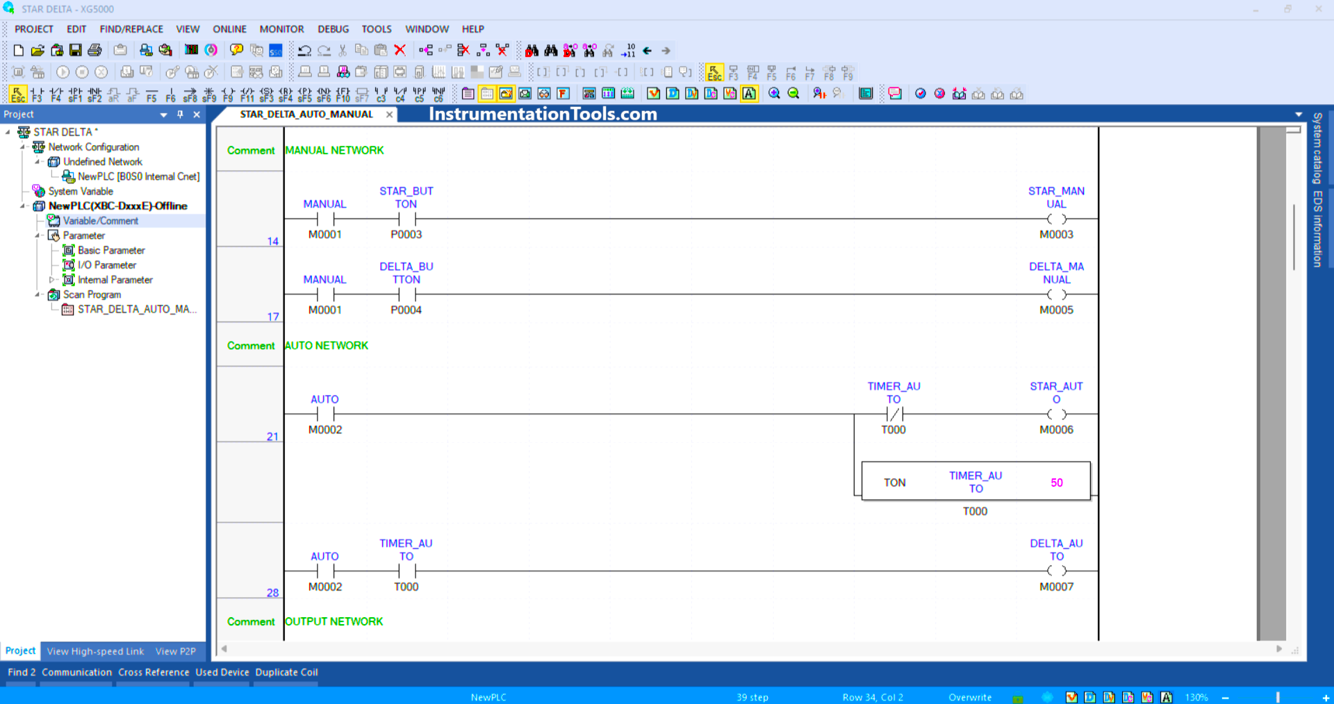
NETWORK 14
In this Rung, when the NO contact of memory bit SYSTEM_ON (M0000) is in the HIGH state and the STAR_BUTTON (P0003) button is Pressed, the memory bit STAR_MANUAL (M0003) will be in the HIGH state.
NETWORKS 17
In this Rung, when the NO contact of memory bit SYSTEM_ON (M0000) is in the HIGH state and the DELTA_BUTTON (P0004) button is Pressed, the memory bit DELTA_MANUAL (M0005) will be in the HIGH state.
NETWORKS 21
In this Rung, when the NO contact of memory bit AUTO (M0002) is in the HIGH state, the memory bit STAR_AUTO (M0006) will be in the HIGH state, and the TIMER_AUTO (T000) timer starts counting up to 5 seconds.
When the timer TIMER_AUTO (T000) finishes counting, the memory bit STAR_AUTO (M0006) changes to a LOW state due to the timer TIMER_AUTO (T000) interlock.
NETWORKS 28
When the NO contact of memory bit AUTO (M0002) and timer TIMER_AUTO (T000) is in the HIGH state, the memory bit DELTA_AUTO (M0007) becomes a HIGH state.
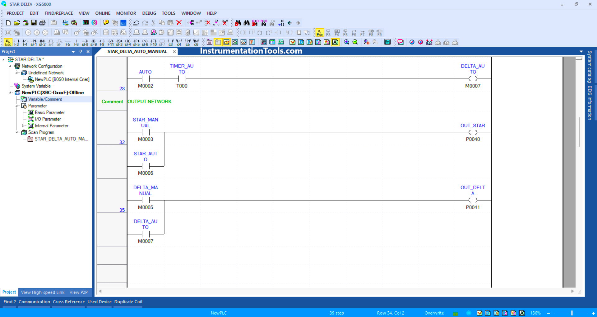
NETWORKS 32
In this Rung, the Output OUT_STAR (P0040) will be ON if the NO contact of memory bit STAR_MANUAL (M0003) or STAR_AUTO (M0006) is in the HIGH state.
NETWORKS 35
In this Rung, the Output OUT_DELTA (P0041) will be ON if the NO contact of memory bit DELTA_MANUAL (M0005) or DELTA_AUTO (M0007) in the HIGH state.
Read Next:
- Motor Running Hours Rockwell PLC Program
- Motor Starter Logic using Siemens PLC Logic
- Structured Text PLC Logic for Motor Interlock
- Siemens VFD Configure TIA Portal Start drive
- Configure PID Controller in Schneider PLC