Inst ToolsInst ToolsInst Tools
  • Ask
  • Courses
  • Videos
  • Q & A
    • Interview
      • Instrumentation
      • Electronics
      • Electrical
      • Practical Questions
    • MCQ
      • Instrumentation MCQ
      • Electrical MCQ
      • Electronics MCQ
      • Control Systems MCQ
      • Analog Electronics MCQ
      • Digital Electronics MCQ
      • Power Electronics MCQ
      • Microprocessor MCQ
      • Multiple Choice Questions
  • EE
    • Electronics
      • Electronics Q & A
      • Electronic Basics
      • Electronic Devices & Circuits
      • Electronics Animation
      • Digital Electronics
    • Electrical
      • Electrical Basics
      • Electrical Q & A
      • Power Electronics
      • Electrical Machines
      • Electrical Animation
      • Power Systems
      • Switchgear & Protection
      • Transmission & Distribution
  • Measure
    • Control Valves
    • Calibration
    • Temperature
    • Pressure
    • Flow
    • Level
    • Analyzers
    • Switches
    • Vibration
    • Solenoid Valve
  • Control
    • PLC Tutorials
    • Control Systems
    • Safety Instrumented System (SIS)
    • Communication
    • Fire & Gas System
  • More
    • Design
    • Tools
    • Animation
    • Basics
    • Formulas
    • Standards
    • TextBooks
    • Common
    • Software
    • Excel Tools
    • Erection & Commissioning
    • Process Fundamentals
    • Videos
    • Books
Search
All rights reserved. Reproduction in whole or in part without written permission is prohibited.
Reading: Snap Acting Relay Working Principle
Share
Notification Show More
Font ResizerAa
Inst ToolsInst Tools
Font ResizerAa
  • Courses
  • PLC Tutorials
  • Control Systems
Search
  • Ask
  • Courses
  • Videos
  • Q & A
    • Interview
    • MCQ
  • EE
    • Electronics
    • Electrical
  • Measure
    • Control Valves
    • Calibration
    • Temperature
    • Pressure
    • Flow
    • Level
    • Analyzers
    • Switches
    • Vibration
    • Solenoid Valve
  • Control
    • PLC Tutorials
    • Control Systems
    • Safety Instrumented System (SIS)
    • Communication
    • Fire & Gas System
  • More
    • Design
    • Tools
    • Animation
    • Basics
    • Formulas
    • Standards
    • TextBooks
    • Common
    • Software
    • Excel Tools
    • Erection & Commissioning
    • Process Fundamentals
    • Videos
    • Books
Follow US
All rights reserved. Reproduction in whole or in part without written permission is prohibited.
Inst Tools > Blog > Control Valves > Snap Acting Relay Working Principle

Snap Acting Relay Working Principle

Last updated: October 3, 2019 11:00 am
Editorial Staff
Control Valves
No Comments
Share
2 Min Read
SHARE

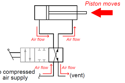
Snap-Acting Relay change ports to switch or lock in secondary air source when the main supply pressure fails below a predetermined set point.

Contents
Snap-Acting RelayArticles You May Like :How Gate Valves Work ?Pressure on Control Valve LiftDouble Acting ActuatorsCage-guided Globe ValveElectric Motor Actuator Parts

In the event of supply or pilot pressure failure, the positive action relay with one common and two inlet or outlet ports will automatically:

  • Switch from main to auxiliary supply pressure
  • Lock an actuator in its last position
  • Extend or retract an actuator stem
  • Divert flow or pressure from one device to another

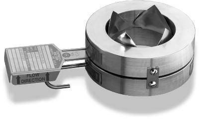
Snap-Acting Relays have an integral pilot which eliminates the extra piping and connections required with other lock-up valves. Compact and lightweight, the relays are easily piped and mounted.

Snap-Acting Relay

Snap Acting Relay Working Principle

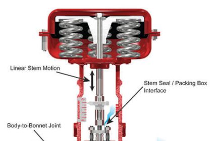
The pressure at which the relays will actuate can be adjusted to any point between 25 PSI (172 kPa) and 85 PSI (586 kPa). Signal or pilot pressure acting in the upper diaphragm overcomes the force of the spring in the bonnet and permits air to flow into the lower chamber.

This pressure buildup forces the spring-loaded spool valve to open common Port “A” to “B”. When the pressure drops below the preset point, the exhaust port opens and common Port “A” is switched from “B” to “C” by releasing the spring loaded spool valve

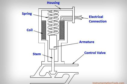
The spool valve will return to its original position (“A” to “B” when the pressure to the pilot is less than or equal to 20% greater than the set point.

For example, if the set pressure is 50 PSI (345 kPa), the unit will return to its original position when the pressure to the pilot builds up to approximately 60 PSI (414 kPa).

Note : The above mentioned pressures are for reference only, These will change as per make/model.

Source : masonika

Articles You May Like :

How Gate Valves Work ?

Pressure on Control Valve Lift

Double Acting Actuators

Cage-guided Globe Valve

Electric Motor Actuator Parts

Don't Miss Our Updates
Be the first to get exclusive content straight to your email.
We promise not to spam you. You can unsubscribe at any time.
Invalid email address
You've successfully subscribed !
Inspection and Test Requirement of Control Valves
Working Principle of Self Operated Valves
What is Split Range Control Loop ?
Solenoid Valve Selection Criteria
How Pilot operated Solenoid Valve Works ?
Share This Article
Facebook Whatsapp Whatsapp LinkedIn Copy Link
Share
Leave a Comment

Leave a Reply Cancel reply

Your email address will not be published. Required fields are marked *

Stay Connected

128.3kFollowersLike
69.1kFollowersFollow
208kSubscribersSubscribe
38kFollowersFollow

Categories

Recent Comments

  • Kamli on Top Free PLC Software
  • Guifty Shimica on Top Non-PLC Certification Courses for Automation Professionals
  • Guifty Shimica on Top Non-PLC Certification Courses for Automation Professionals
  • MIHARITSOA Aina Sitraka on Top Non-PLC Certification Courses for Automation Professionals

Related Articles

Dome Valve Principle

Dome Valve Working Principle

What is Partial Stroke Test

What is Partial Stroke Test?

Ball Valve Parts

What is Ball Valve ?

Valve Technician Interview Questions

Valve Technician Interview Questions

Fail-Close Valve

What is a Fail-Close Valve? – Advantages and Disadvantages

Control valve characteristics

Valve Characteristics – Quick Opening, Linear & Equal Percentage

Typical schematic of Butterfly valve

Automated Block Valve (ABV)

Root Cause Analysis for Valve Problem

Root Cause Analysis for Tank Overflow due to Valve Problem

More Articles

Studio 5000 Tutorial PLC Programming for Digital Alarms

Studio 5000 Tutorial: PLC Programming for Digital Alarms

Single-beam non-dispersive analyzer

Single-beam Non-dispersive Analyzer

Pressure Sensor Temperature Effects

Temperature Compensation for Pressure Measurement

Sick Flow meters

Flare Ultrasonic Flow Meter – SOPAS Engineering Tool

What we need to Know before Tune a PID Controller

What we need to Know before Tune a PID Controller ?

Single Beam and Double Beam Instruments

Single Beam and Double Beam Instruments

Measurement of Phase Angle Objective Questions

Measurement of Phase Angle Objective Questions

Function Block Program Simulation

What are Functions in PLC Programming? (FCs)

Follow US
All rights reserved. Reproduction in whole or in part without written permission is prohibited.
Welcome Back!

Sign in to your account

Username or Email Address
Password

Lost your password?