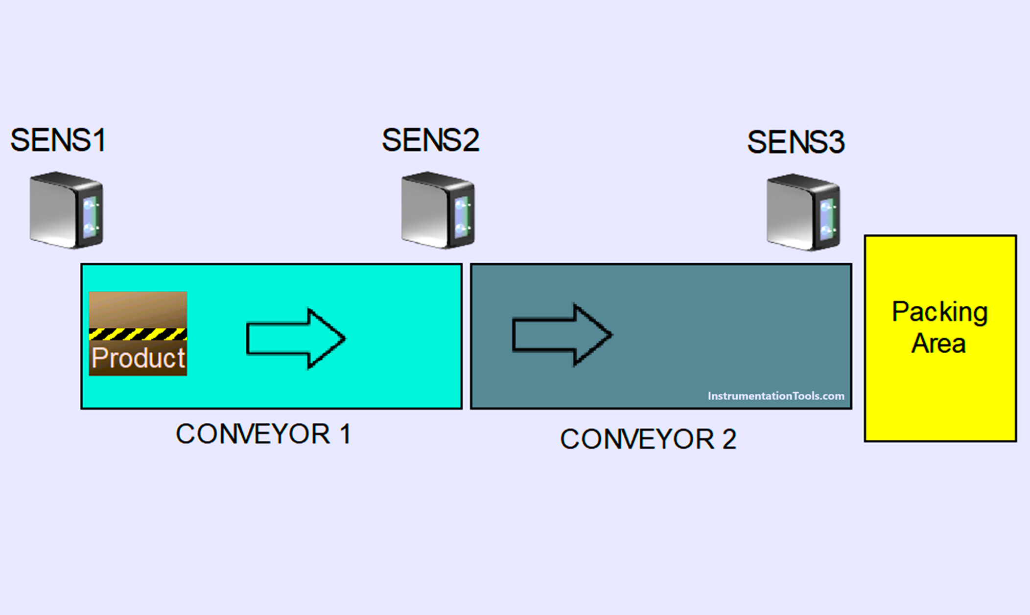
This article discusses a simple automation system using conveyors to transport products in the manufacturing process. This system consists of two conveyor sections that run sequentially: the first conveyor is activated when receiving the product, then the second conveyor starts operating after receiving the product from the first conveyor. Once the product reaches its final destination in the Packing Area, both conveyors will Stop and the amount of product that has been transferred will be recorded.
Simple Conveyor Control PLC Program
In this program, the Input Devices used are as follows:
- The PB_START (P00000) button is used to turn ON the system.
- The PB_STOP (P00001) button is used to turn OFF the system.
- The RESET_COUNTER (P00005) button is used to Reset the counter data.
- Sensor SENS1 (P00002) is used to detect products on Conveyor-1.
- Sensor SENS2 (P00003) is used to detect products on Conveyor-2.
- Sensor SENS3 (P00004) is used to detect products that have arrived at their final destination (Packing area).
Sequence-1
After the system is turned ON, Conveyor CONVEYOR1 (P00040) will Run if the SENS1 (P00002) sensor is Active because it detects the product.
Sequence-2
Conveyor CONVEYOR2 (P00041) will Start Running when Sensor SENS2 (P00003) has detected the product sent by Conveyor CONVEYOR1 (P00040).
When the product has arrived at the final destination area, the sensor SENS3 (P00004) will be Active because it detects the product, so that the Conveyor CONVEYOR1 (P00040) and CONVEYOR2 (P00041) Stop.
Next, the product will be counted in the memory word COUNTER (D00000).
Conveyor CONVEYOR1 (P00040) will Stop Running if within 5 seconds after Sensor SENS1 (P00002) is Active, Sensor SENS2 (P00003) does not detect the presence of the product that has been sent.
Addressing of PLC
| Comment | Input (I) | Output (Q) | Memory Word | Memory Bits | Timer |
| PB_START | P00000 | ||||
| PB_STOP | P00001 | ||||
| RESET_COUNTER | P00005 | ||||
| SENS1 | P00002 | ||||
| SENS2 | P00003 | ||||
| SENS3 | P00004 | ||||
| CONVEYOR1 | P00040 | ||||
| CONVEYOR2 | P00041 | ||||
| COUNTER | D00000 | ||||
| TIMER1 | T0000 | ||||
| SYSTEM_ON | M00000 |
PLC Programming
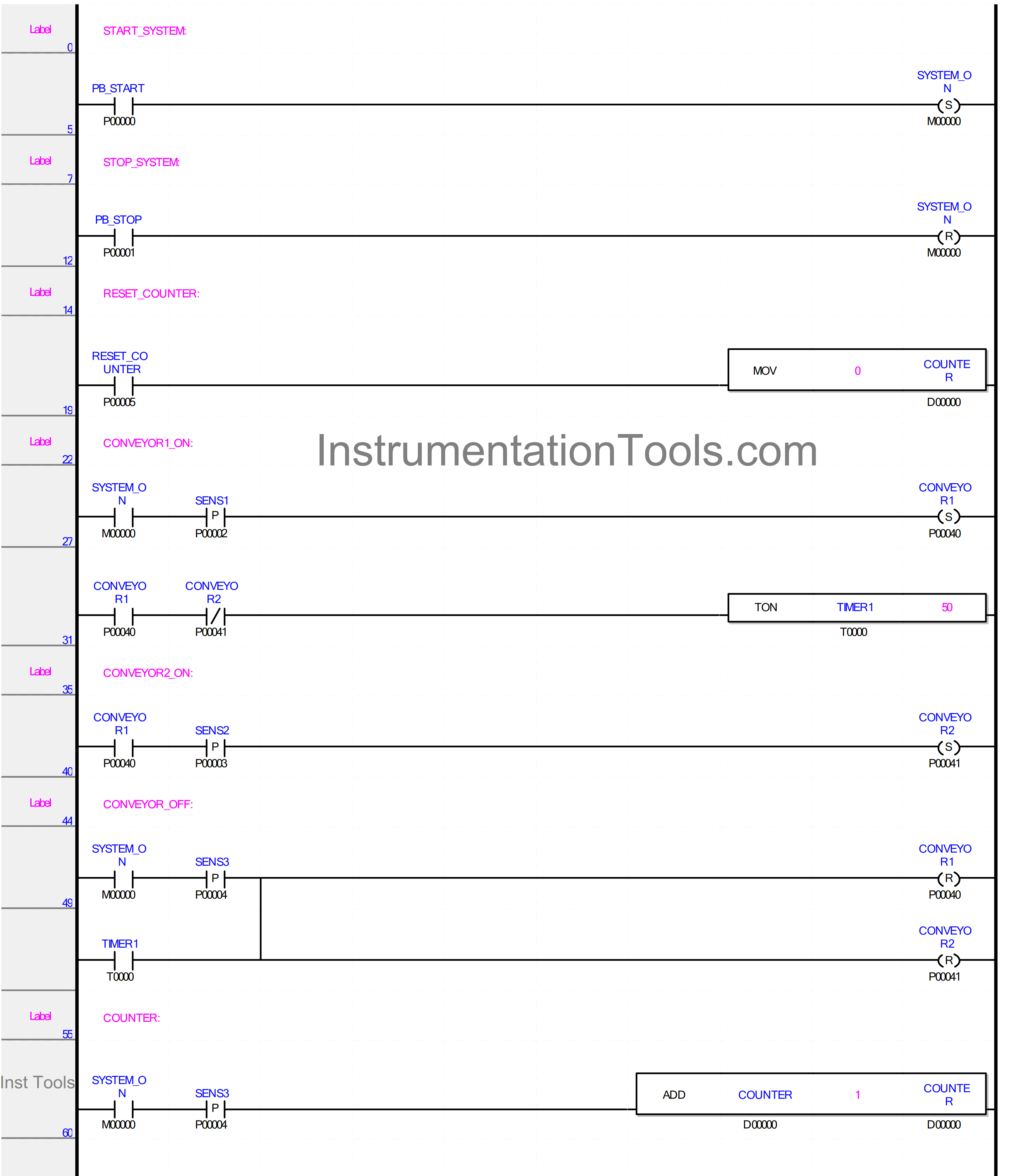
RUNG 5
In this Rung, the memory bit SYSTEM_ON (M00000) will be in the HIGH state if the PB_START (P00000) button is Pressed.
The memory bit SYSTEM_ON (M00000) will remain in the HIGH state even though the PB_START (P00000) button has been Released because it uses the SET Coil Instruction.
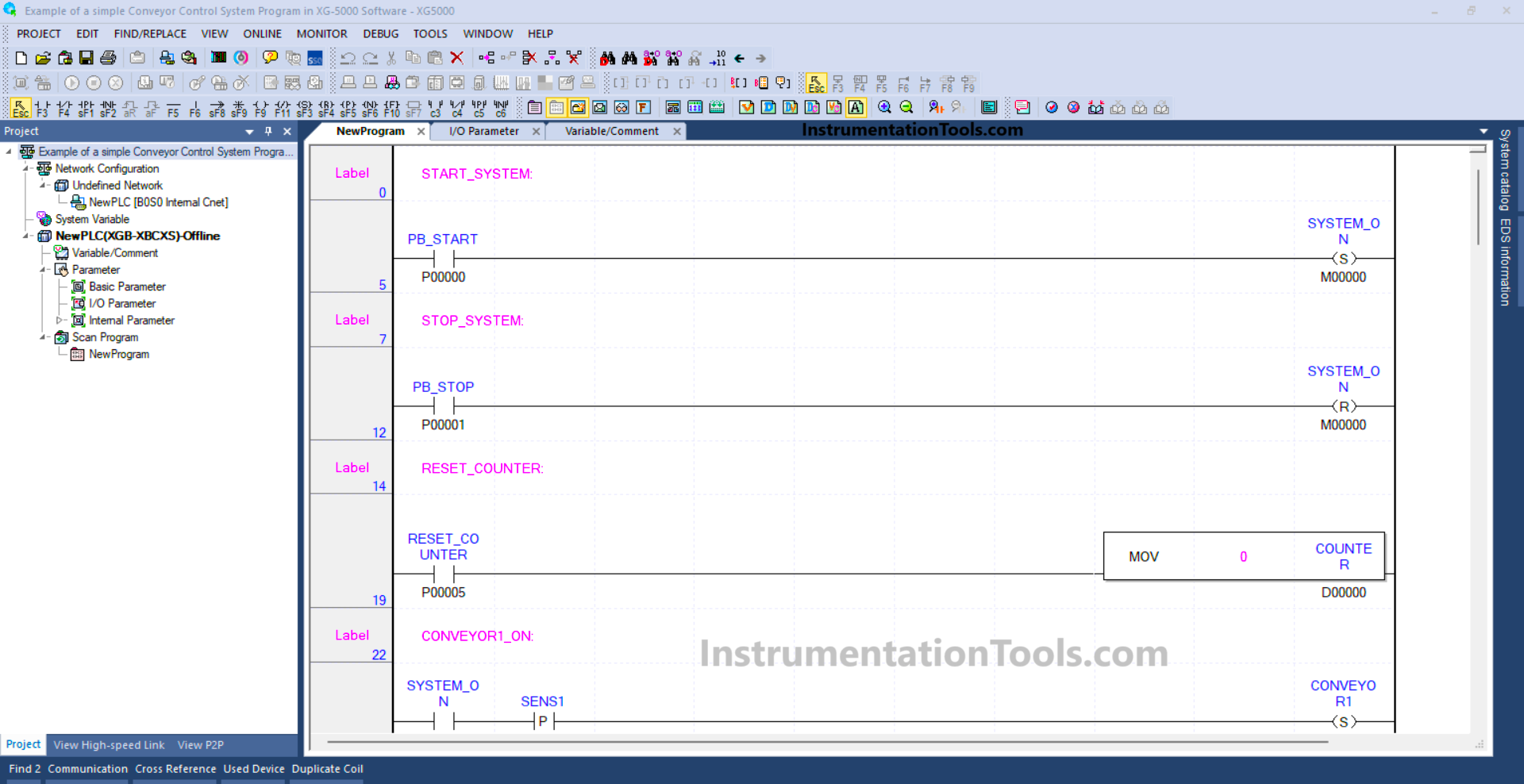
RUNG 12
In this Rung, if the PB_STOP (P00001) button is Pressed, the memory bit SYSTEM_ON (M00000) will be in the LOW state. Because it uses the RESET Coil Instruction.
RUNG 19
In this rung, the value in memory word COUNTER (D00000) will be Reset to zero “0” if the RESET_COUNTER (P00005) button is Pressed. Because the MOV instruction moves the zero value “0” to the memory word COUNTER (D00000).
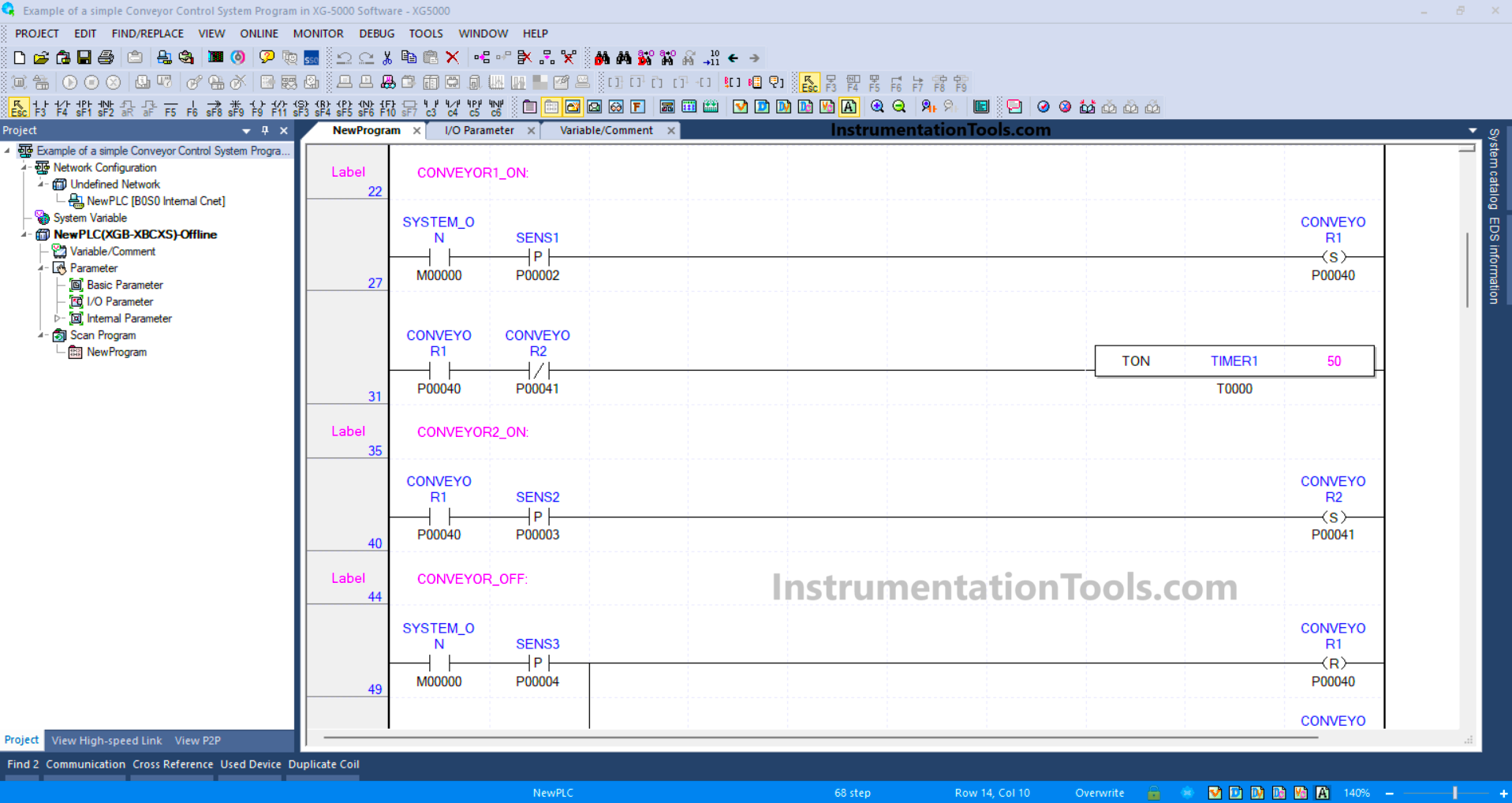
RUNG 27
In this Rung, Output CONVEYOR1 (P00040) will be ON when the NO contact of memory bit SYSTEM_ON (M00000) and Sensor SENS1 (P00002) in the HIGH state.
The CONVEYOR1 (P00040) output will remain in the ON state even though the Sensor SENS1 (P00002) in the LOW state, because it uses the SET Coil Instruction.
RUNG 31
In this Rung, when the NO contact of Output CONVEYOR1 (P00040) is ON, the TIMER1 (T0000) Timer will Start counting up to 5 seconds. if the NC contact of Output CONVEYOR2 (P00041) is ON, then Timer TIMER1 (T0000) will be OFF.
RUNG 40
Output CONVEYOR2 (P00041) will be ON when the NO contact of Output CONVEYOR1 (P00040) is ON and Sensor SENS2 (P00003) in HIGH state.
The CONVEYOR2 (P00041) Output will remain in the ON state even though the Sensor SENS2 (P00003) in the LOW state, because it uses the SET Coil Instruction.
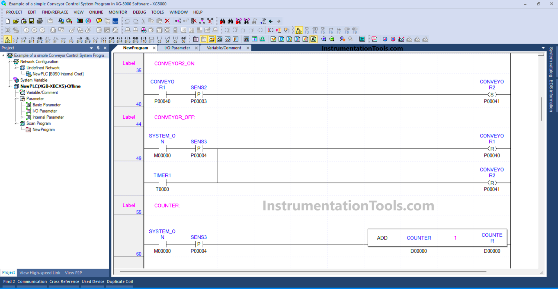
RUNG 49
In this rung, when the NO contact of the SYSTEM_ON memory bit (M00000) and Sensor SENS3 (P00004) are in a HIGH state, the outputs CONVEYOR1 (P00040) and CONVEYOR2 (P00041) will turn OFF.
This is because in this rung, the outputs CONVEYOR1 (P00040) and CONVEYOR2 (P00041) use the RESET Coil instruction.
RUNG 60
In this rung, the value in the memory word COUNTER (D00000) will increase (+1) if the NO contact of the SYSTEM_ON memory bit (M00000) and Sensor SENS3 (P00004) are in a HIGH state.
Read Next:
- PLC Logic Train Detection and Gate Operation
- Weighing with Labeling PLC Automation Logic
- Functional Block Diagram Analog Alarm Logic
- Timer-Based Sequential PLC Programming
- PLC Programming for Baking with Auto Mode