Inst ToolsInst ToolsInst Tools
  • Courses
  • Automation
    • PLC
    • Control System
    • Safety System
    • Communication
    • Fire & Gas System
  • Instrumentation
    • Design
    • Pressure
    • Temperature
    • Flow
    • Level
    • Vibration
    • Analyzer
    • Control Valve
    • Switch
    • Calibration
    • Erection & Commissioning
  • Interview
    • Instrumentation
    • Electrical
    • Electronics
    • Practical
  • Q&A
    • Instrumentation
    • Control System
    • Electrical
    • Electronics
    • Analog Electronics
    • Digital Electronics
    • Power Electronics
    • Microprocessor
  • Request
Search
  • Books
  • Software
  • Projects
  • Process
  • Tools
  • Basics
  • Formula
  • Power Plant
  • Root Cause Analysis
  • Electrical Basics
  • Animation
  • Standards
  • 4-20 mA Course
  • Siemens PLC Course
Reading: Shunt Calibration of a Strain Gauge Load Cell
Share
Font ResizerAa
Inst ToolsInst Tools
Font ResizerAa
  • Courses
  • Design
  • PLC
  • Interview
  • Control System
Search
  • Courses
  • Automation
    • PLC
    • Control System
    • Safety System
    • Communication
    • Fire & Gas System
  • Instrumentation
    • Design
    • Pressure
    • Temperature
    • Flow
    • Level
    • Vibration
    • Analyzer
    • Control Valve
    • Switch
    • Calibration
    • Erection & Commissioning
  • Interview
    • Instrumentation
    • Electrical
    • Electronics
    • Practical
  • Q&A
    • Instrumentation
    • Control System
    • Electrical
    • Electronics
    • Analog Electronics
    • Digital Electronics
    • Power Electronics
    • Microprocessor
  • Request
Follow US
All rights reserved. Reproduction in whole or in part without written permission is prohibited.
Inst Tools > Blog > Calibration > Shunt Calibration of a Strain Gauge Load Cell

Shunt Calibration of a Strain Gauge Load Cell

Last updated: August 22, 2019 7:44 am
Editorial Staff
Calibration
No Comments
Share
4 Min Read
SHARE

Shunt calibration is the known electrical unbalancing of a strain gauge bridge by means of a fixed resistor that is placed, or “shunted,” across one leg of the bridge.

The Wheatstone Bridge used in strain gauge load cells are typically field-calibrated using the shunt calibration technique.

Shunt calibration is a method of periodically checking the gain or span of a signal conditioner, which is used in conjunction with a strain gauge based transducer, without exposing the transducer to known, traceable, physical input values.

If required, adjustments can then be made to the signal conditioner to insure accurate measurement results

A strain gauge bridge is “in balance” when the host mechanical structure is unloaded and unstressed.

As the host structure (diaphragm, bending beam, shear beam, column, etc.) is loaded or stressed, the Wheatstone Bridge becomes unbalanced, resulting in an output signal that is proportional to the applied load.

Calibration of a Strain Gage Load Cell

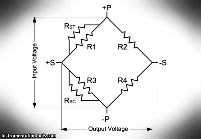
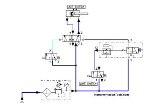
Fig : A Wheatstone Bridge circuit showing the location for connecting the appropriate shunt resistor for the purpose of simulating either a tension or compression input.

Shunt calibration stimulates the mechanical input to a transducer by unbalancing the bridge with a fixed resistor placed across, or in parallel with, one leg of the bridge.

For tension shunt calibration, the shunt resistor (RST) is shunted across the +excitation (+P) and +signal (+S) leg of the bridge.

For a compression shunt calibration, the shunt resistor (RSC) is shunted across the – excitation (-P) and +signal (+S) leg of the bridge.

Calibration Procedure :

Here are step-by-step instructions for shunt calibration of a strain gauge load cell.

1. Connect the transducer to an appropriate strain gauge signal conditioner and allow adequate time for the system to stabilize.

2. Apply a full-scale N.I.S.T. traceable, mechanical input (or load) to the transducer.

3. Adjust the signal conditioner’s gain or span controls, as required, to obtain a full-scale electrical output signal, and/or numeric display that represents the applied, mechanical input quantity.

4. Remove the mechanical input (or load).

5. Place a shunt calibration resistor across an appropriate leg of the Wheatstone Bridge (as discussed above).

6. Record the value of the signal conditioner’s output signal and/or numeric display. This value is the shunt calibration value, or equivalent load.

7. It is important to note that the shunt calibration value is specific for the particular shunt resistor used.This value, and the particular resistor, are now matched to the transducer and form the basis of the transferable shunt calibration.

Summary

Shunt calibration is accepted throughout the industry as means of periodic calibration of a signal conditioner and transducer between calibrations of known, applied, traceable, mechanical, input values.

Consequently, most all strain gauge transducer manufacturers collect and supply shunt calibration data, along with a shunt calibration resistor, as a standard feature.

Source : PCB Load & Torque Division

Don't Miss Our Updates
Be the first to get exclusive content straight to your email.
We promise not to spam you. You can unsubscribe at any time.
Invalid email address
You've successfully subscribed !

Continue Reading

Hybrid Level Measurement Principle, Selection, Installation, Limitations and Calibration
Level Transmitter Calibration Procedure
Pig Signalling Switches Functional Testing
How-to do Control Valve Calibration?
Instrument Turndown Ratio
What is Bump Testing ?
Share This Article
Facebook Whatsapp Whatsapp LinkedIn Copy Link
Share
Leave a Comment

Leave a Reply Cancel reply

Your email address will not be published. Required fields are marked *

Stay Connected

128.3kFollowersLike
69.1kFollowersFollow
210kSubscribersSubscribe
38kFollowersFollow

Categories

Explore More

What is Field Transmitter Damping ?
Difference between Accuracy, Tolerance, Uncertainty, and Error
Fieldbus Transmitters Calibration and Ranging
Important Terms in Calibration
Error sources creating uncertainty in Calibration
Displacer Level Transmitter Calibration using Water & Process Liquid
Closed tank DP Level Transmitter with wet leg elevation zero direct mount Calibration
Displacer Level Transmitter Dry Calibration with Weights

Keep Learning

RTD Testing Methods

RTD Testing Methods in Calibration Laboratory

Stability and Uniformity of Temperature Bath

Stability and Uniformity of Temperature Bath

Pressure Gauge Calibration Procedure

Calibration and Troubleshooting of Oxygen Analyzer

Calibration and Troubleshooting of Oxygen Analyzer

Motor Operated Valve Functional Testing

Motor Operated Valve Functional Testing

dissolved-oxygen-probe-calibration-procedure

Dissolved oxygen probe calibration procedure

Importance of Unit Measurement

Importance of Unit Measurement

How to Calibrate Load Cells

How to Calibrate Load Cells in Weighing Applications?

Learn More

Introduction of Urea Bagging machine

Introduction to Urea Bagging Machine

Bernoulli's Principle and Flow Meters

Top Questions on Bernoulli’s Principle in Flow Meters

Plant Engineering Drawings

Piping and Instrumentation Drawing (P&ID) Tutorials – Part 1

Questions & Answers of Power Systems

Questions & Answers of Power Systems

Instrumentation Android App

Advantages of Pneumatic Systems in the Automotive Industry

Advantages of Pneumatic Systems in the Automotive Industry

Venturi Flow Meter Theory

Basics of Venturi Flow Meter

4-20mA VFD Drive Formula

4-20mA Linear Conversion Calculation for VFD Drive (Formula)

Menu

  • About
  • Privacy Policy
  • Copyright

Quick Links

  • Learn PLC
  • Helping Hand
  • Part Time Job

YouTube Subscribe

Follow US
All rights reserved. Reproduction in whole or in part without written permission is prohibited.
Welcome Back!

Sign in to your account

Username or Email Address
Password

Lost your password?