The device which operates at above 30V is called an electrical device and the device which operates with less than 30V is called electronic voltage. Even though the electronic devices like transistors are used to amplify the analog signals, they eventually need DC voltage biasing to perform that task. Likewise so many electronic devices operate on only DC which cannot sustain any voltage changes. The DC sources like batteries can be used to power these electronic devices but the batteries will be drained with the time which provides interruption.
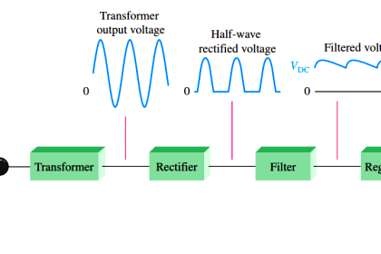
In our electricity generation all the generated energy is alternating in nature, so this alternating energy should be converted in to direct energy to provide DC supply to the electronic components. This is an online process where the generated AC is converted into proper regulated DC. It is so important to learn the two devices called rectifiers and filters which are used to convert AC to DC.
Rectifiers
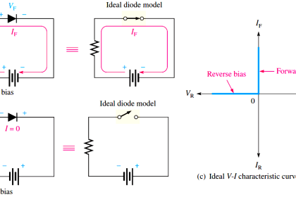
The device which converts alternating (bidirectional) voltage to pulsating (Unidirectional) voltage is called rectifier. As the name specifies it rectifies some portion of the alternating signal and provides a unidirectional signal at the output. This is achieved by the electronic element called semiconductor diode. The semiconductor diode is the element which allows the signal in one direction and blocks the signal in reverse direction i.e. converting bidirectional into unidirectional.
Half Wave Rectifier
However a simple diode can acts as rectifier which also can be called as Half wave rectifier. But the half wave rectifier can convert half of the input signal to pulsating DC and the remaining half will be lost as heat. So the efficiency is less.
Full wave Rectifier
To increase the efficiency two diodes are placed to convert each AC cycle into pulsating DC cycle. I.e. two unidirectional pulsed for one AC cycle will be produced at the output. The full wave rectifiers are divided as Center-taped full wave rectifier and Bridge Full wave rectifier.
Center Taped full wave rectifier
In this the center taped transformer is used to perfectly divide the AC signal in to half cycles and to give as an input to the two diodes which produces the pulsating DC.
Bridge Rectifier
Four rectifier diodes arranged in the form of bridge in which two diodes conducts per one half AC cycle and provides the pulsating DC output with two pulses per cycle. Here the need of the transformer is eliminated.
However the rectifier output is unidirectional pulsating current which has variation in magnitude. This variation in magnitude should be eliminated before giving to any electronic component. So to eliminate this, the devices called filters are introduced.
Filters
The devices which converts the pulsating DC in to pure DC is called filter. As the name specifies it filters the oscillations in the signal and provides a pure DC at the output. The electronic reactive elements like capacitor and inductors are used to do this work.
Inductive Filter (L)
The property of the inductor is that it opposes any sudden change that occurs in a circuit an provides a smoothed output. In the case of AC, there is change in the magnitude of current with time. So the inductor offers some impendence (opposing force) for AC ((XL = jwL) and offers shot circuit for DC. So by connecting inductor in series with the supply blocks AC and allows DC to pass.
Capacitor Filter
The elegant quality of the capacitor is it stores the electrical energy for short time and discharges it. By controlling the charging and discharging rate of the capacitor the pure DC can be obtained from the pulsating DC. In simple the capacitor allows AC and blocks DC, so the capacitor can connect parallel to the power supply so that the AC is filtered out and DC will reach the load.
LC Filter
In the above two filters the reactive components are singly connected, however no element will be perfect in doing the job i.e. inductor in series may pass small quantity of AC and Capacitor in parallel may not block all the AC component. So for better filtering two components are connected as filter which provides less ripple factor at the output compared to the above filter.
CLC or π filter
In L and LC filter the inductor connected in series to the power supply drops more AC voltage which reduces the efficiency. So to avoid this increase the efficiency a capacitor is connected at the input of the LC filter. The input capacitor charges & discharges and provides a ripple DC at the input of inductor. Then the drop at the inductor is less and provides a ripple less DC which again filtered by capacitor at the output.
Multiple connection the above filter provides better efficiency and less ripple factor at the output.