Inst ToolsInst ToolsInst Tools
  • Courses
  • Automation
    • PLC
    • Control System
    • Safety System
    • Communication
    • Fire & Gas System
  • Instrumentation
    • Design
    • Pressure
    • Temperature
    • Flow
    • Level
    • Vibration
    • Analyzer
    • Control Valve
    • Switch
    • Calibration
    • Erection & Commissioning
  • Interview
    • Instrumentation
    • Electrical
    • Electronics
    • Practical
  • Q&A
    • Instrumentation
    • Control System
    • Electrical
    • Electronics
    • Analog Electronics
    • Digital Electronics
    • Power Electronics
    • Microprocessor
  • Request
Search
  • Books
  • Software
  • Projects
  • Process
  • Tools
  • Basics
  • Formula
  • Power Plant
  • Root Cause Analysis
  • Electrical Basics
  • Animation
  • Standards
  • 4-20 mA Course
  • Siemens PLC Course
Reading: Short Circuit and Open Circuit
Share
Notification Show More
Font ResizerAa
Inst ToolsInst Tools
Font ResizerAa
  • Courses
  • Design
  • PLC
  • Interview
  • Control System
Search
  • Courses
  • Automation
    • PLC
    • Control System
    • Safety System
    • Communication
    • Fire & Gas System
  • Instrumentation
    • Design
    • Pressure
    • Temperature
    • Flow
    • Level
    • Vibration
    • Analyzer
    • Control Valve
    • Switch
    • Calibration
    • Erection & Commissioning
  • Interview
    • Instrumentation
    • Electrical
    • Electronics
    • Practical
  • Q&A
    • Instrumentation
    • Control System
    • Electrical
    • Electronics
    • Analog Electronics
    • Digital Electronics
    • Power Electronics
    • Microprocessor
  • Request
Follow US
All rights reserved. Reproduction in whole or in part without written permission is prohibited.
Inst Tools > Blog > Electronic Devices & Circuits > Short Circuit and Open Circuit

Short Circuit and Open Circuit

Last updated: November 21, 2017 1:40 pm
Editorial Staff
Electronic Devices & Circuits
1 Comment
Share
1 Min Read
SHARE

The Short-Circuit

Consider a resistor whose value is zero ohms. An equivalent representation of such a resistance, called a short-circuit, is shown below:

Short Circuit and Open Circuit

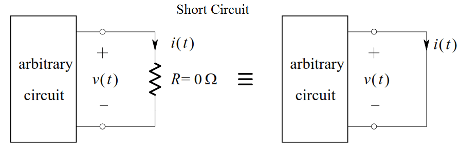
By Ohm’s Law:  ( For short Circuit, R = 0 )

v = Ri  = 0i = 0 V

Thus, no matter what finite value i(t ) has, v(t ) will be zero. Hence, we see that a zero-ohm resistor is equivalent to an ideal voltage source whose value is zero volts, provided that the current through it is finite.

The Open-Circuit

Consider a resistor having infinite resistance. An equivalent representation of such a resistance, called an open-circuit, is shown below:

Open Circuit

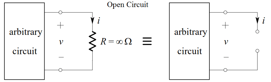
By Ohm’s Law:  ( For short Circuit, R = ∞ )

i = v/R  = v/∞ = ∞ A

Thus, no matter what finite value v(t ) has, i(t ) will be zero. Thus, we may conclude that an infinite resistance is equivalent to an ideal current source whose value is zero amperes, provided that the voltage across it is finite

Don't Miss Our Updates
Be the first to get exclusive content straight to your email.
We promise not to spam you. You can unsubscribe at any time.
Invalid email address
You've successfully subscribed !

Continue Reading

Basics of Ohm’s Law
JFET Working Animation
Energy Diagrams of PN Junction & Depletion Region
pi filter Operation
Transistor Voltage Divider Bias
N Type and P Type Semiconductors
Share This Article
Facebook Whatsapp Whatsapp LinkedIn Copy Link
Share
1 Comment
  • Warren says:
    April 15, 2020 at 5:13 am

    Do they sell an electrical circuit finder to locate a short in a wall or ceiling? ware I can disconnect the wire from the 15 amp breaker and disconnect the neutral white wire and use alligator clams on both wires then use the monitor to locate the open or short circuit? Thanks, Warren

    Reply

Leave a Reply Cancel reply

Your email address will not be published. Required fields are marked *

Stay Connected

128.3kFollowersLike
69.1kFollowersFollow
210kSubscribersSubscribe
38kFollowersFollow

Categories

Explore More

Transistor Base Bias
Electron Gun of Cathode Ray Tube
Summary Of Transistor Bias Circuits
Power MOSFET
Capacitor Filter Working Principle
Transistor Collector Characteristic Curves
Semiconductors Diodes Questions & Answers
Testing a Transistor with a Digital Multimeter

Keep Learning

Combining Independent Current Sources in Parallel

Combining Independent Current Sources in Parallel

energy-diagrams-for-insulator-semiconductor-and-conductor

Band Gap for Semiconductor Materials

What is a Memristor

What is a Memristor? Principle, Advantages, Applications

Laser Diode Working Principle

Laser Diode Working Principle

Tunnel Diode

Tunnel Diode Working Principle

Zener Diode

Zener Diode Breakdown Characteristics

Shockley Diode Working Principle

Shockley Diode Working Principle

Transistor Amplifier Working Principle

Learn More

What is a Wet Contact in PLC

What is a Wet Contact? – Basics of PLC Wiring

Industrial Sensors

Sensors Handbook

Simulation in Machine Expert HVAC

How to do Simulation in Schneider PLC?

DRUM DB

Siemens Drum block for Sequencer Operation

Use Cryptographic checks for PLC

#5 PLC Best Practices – Cryptographic and Checksum Integrity Checks

Difference Between Microcontroller and Microprocessor

Difference Between Microcontroller and Microprocessor

Orifice Flow Meter With DP Transmitter

What is an Orifice Meter?

Top 200 Electrical Engineers Objective Questions and Answers

Top 200 Electrical Engineers Objective Questions and Answers

Menu

  • About
  • Privacy Policy
  • Copyright

Quick Links

  • Learn PLC
  • Helping Hand
  • Part Time Job

YouTube Subscribe

Follow US
All rights reserved. Reproduction in whole or in part without written permission is prohibited.
Welcome Back!

Sign in to your account

Username or Email Address
Password

Lost your password?