We have seen how a seven segment display plays a very important role in many types of indications that we see in our daily lives. If we need to control its logic through PLC, then a new programmer has many options to choose from the language to write it. One of the most highly used and efficient level languages is structured text.
In this post, we will see how to write a seven segment display logic in a PLC program using structured text language.
Seven Segment Display

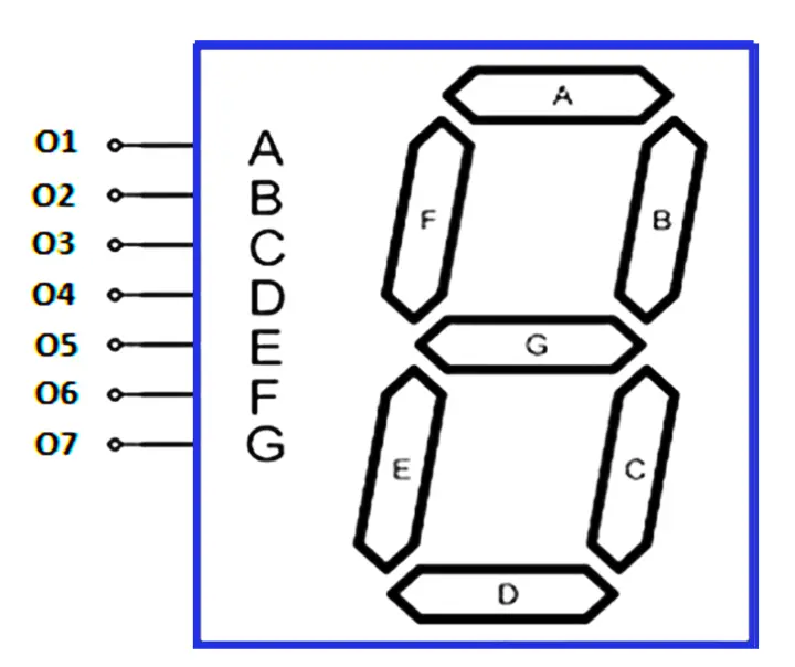
Let us understand the case scenario first. There are four PLC digital inputs and seven PLC digital outputs. For a number to be displayed, the inputs will come in sequence as per the below truth table.
In correspondence to the input sequence received, the outputs will turn on accordingly and display the LED segment with numbers. Refer to the second image for more understanding, where you can co-relate this table with the display.
| Input I0 | Input I1 | Input I2 | Input I3 | Output O1 | Output O2 | Output O3 | Output O4 | Output O5 | Output O6 | Output O7 | Display |
| 0 | 0 | 0 | 0 | 1 | 1 | 1 | 1 | 1 | 1 | 0 | 0 |
| 0 | 0 | 0 | 1 | 0 | 1 | 1 | 0 | 0 | 0 | 0 | 1 |
| 0 | 0 | 1 | 0 | 1 | 1 | 0 | 1 | 1 | 0 | 1 | 2 |
| 0 | 0 | 1 | 1 | 1 | 1 | 1 | 1 | 0 | 0 | 1 | 3 |
| 0 | 1 | 0 | 0 | 0 | 1 | 1 | 0 | 0 | 1 | 1 | 4 |
| 0 | 1 | 0 | 1 | 1 | 0 | 1 | 1 | 0 | 1 | 1 | 5 |
| 0 | 1 | 1 | 0 | 1 | 0 | 1 | 1 | 1 | 1 | 1 | 6 |
| 0 | 1 | 1 | 1 | 1 | 1 | 1 | 0 | 0 | 0 | 0 | 7 |
| 1 | 0 | 0 | 0 | 1 | 1 | 1 | 1 | 1 | 1 | 1 | 8 |
| 1 | 0 | 0 | 1 | 1 | 1 | 1 | 1 | 0 | 1 | 1 | 9 |
Programming with Structured Text
Now, let us write this program. Refer to the below image. In the first four lines, we are moving the values of four inputs in the corresponding bits of a single word. Due to this, we get different values of the word.
The value of this word is the same as the display number.
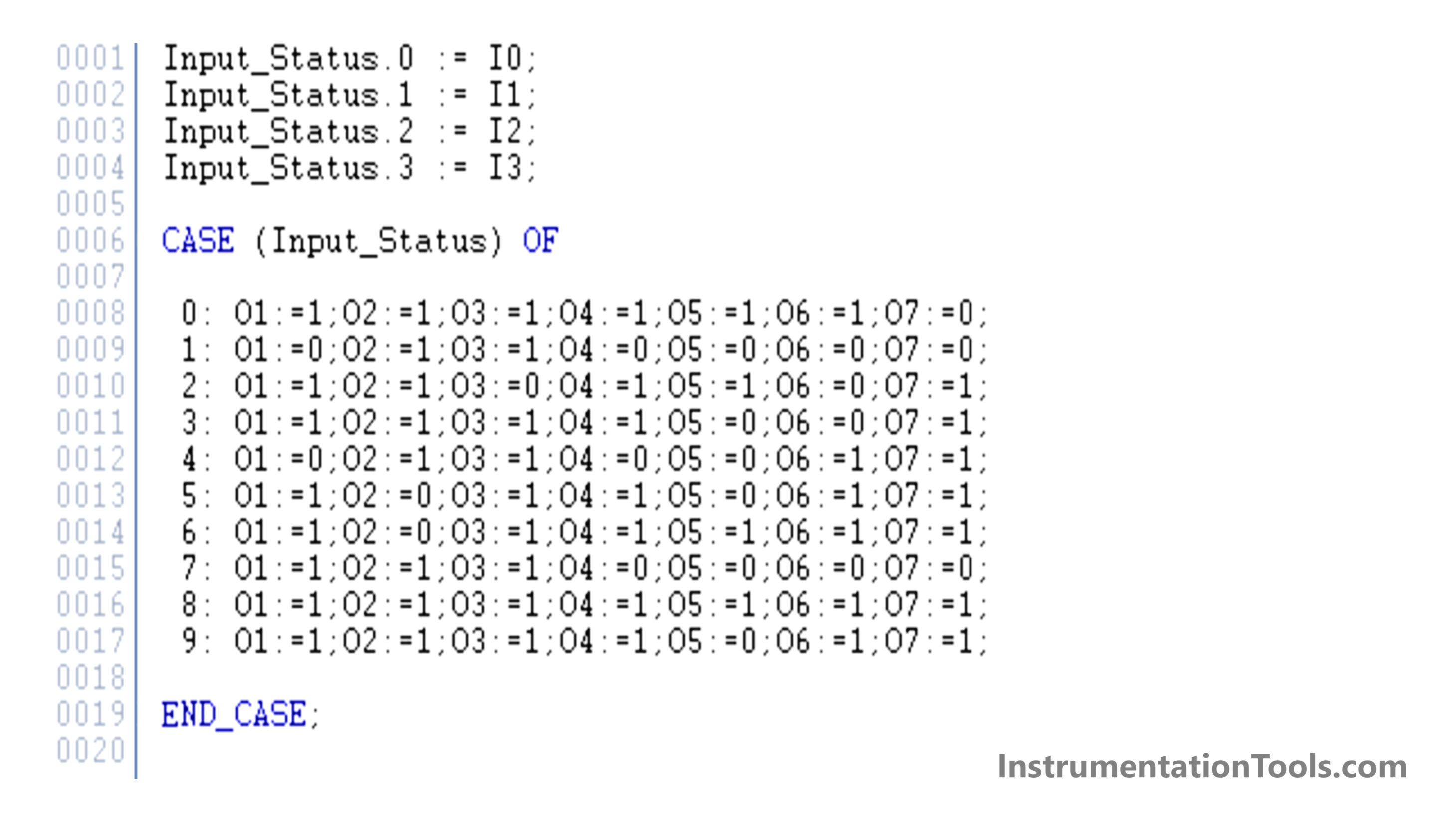
Now, after these first four lines, we are using a case statement. A case statement is used to execute different conditions based on the value of the variable referred. In our case, we are referring to the input status variable. So, based on its current value, we write 0 or 1 to the seven outputs. Each case value ends with “:” and each statement ends with “;”.
Basically, we are just moving true or false values in the digital outputs based on the input conditions. Whatever may be the input value, it will write a corresponding value to the word and this word will then be used as a reference for writing the outputs.
In place of case statements, we can also use if-else statements. But then, the logic would have become a little bulkier and larger to look at. This means, that we would have to write a total of 10 if conditions for the logic. So, we simplified it more by using a case statement.
This logic looks simple in structured text. Imagine using it in ladder language. We would have to write so many rungs with various parallel conditions for turning the output on.
Task For You: Now program the 7 segment display to show the alphabets as shown in the above animation.
In this way, we saw how to write a seven-segment display logic in a PLC program using structured text language.
Read Next:
- Structured Text PLC Logic for Motor Interlock
- How Modbus is used in Industrial Networks?
- Conveyor Speed Logic using Structured Text
- Burglar Alarm Security System PLC FBD Logic
- Car Wash Program Functional Block Diagram
