Combining Resistors
Relatively complicated resistor combinations can be replaced by a single equivalent resistor whenever we are not specifically interested in the current, voltage or power associated with any of the individual resistors.
Series Resistors
Consider the series combination of N resistors shown in (a) below:
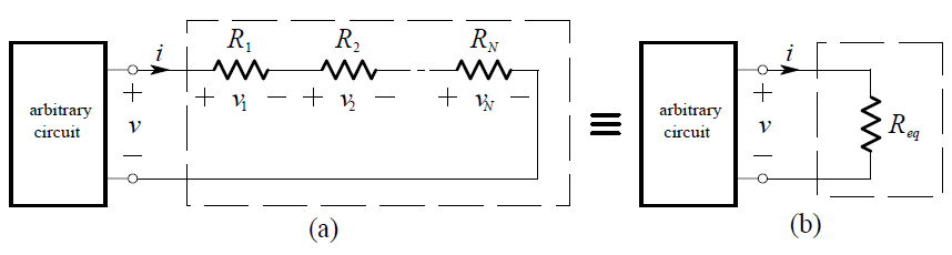
We apply KVL:
v = v1 + v2 + … vN
and Ohm’s Law:
v = R1i + R2i + … RN i
= (R1 + R2 + … RN )i
and then compare this result with the simple equation applying to the equivalent circuit shown in above Figure
v = Req . i
Thus, the value of the equivalent resistance for N series resistances is:
Req = R1 + R2 + …+ RN
Parallel Resistors
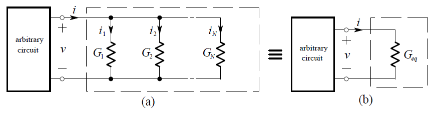
We apply KCL:
i = i1 + i2 + … iN
and Ohm’s Law:
i = G1v + G2v + …GN v
= (G1 + G2+ …GN )v
whereas the equivalent circuit shown in above Figure
i = Geq v
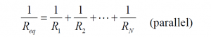
and thus the value of the equivalent conductance for N parallel conductances is:
Geq = G1 + G2 + … + GN (parallel)
In terms of resistance instead of conductance
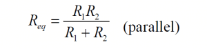
The special case of only two parallel resistors is needed often:
Combining two resistors in parallel
Note that since Geq = G1 + G2 then we may deduce that:
Geq > G1 and Geq > G2
Hence:
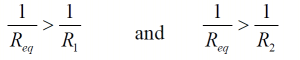
or:
Req < R1 and Req < R2
Thus the equivalent resistance of two resistors in parallel is less than the value of either of the two resistors.
The special case of N resistors of equal value R in parallel is:

Example
We want to find the current i in the circuit below:
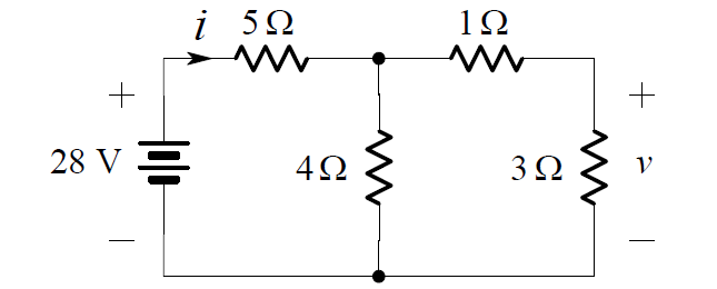
In order to find i, we can replace series and parallel connections of resistors by their equivalent resistances. We begin by noting that the 1 W are in series. Combining them we obtain: are in series. We begin by noting that the 1 ohm are 3 ohm are in series. Combining them we obtain:
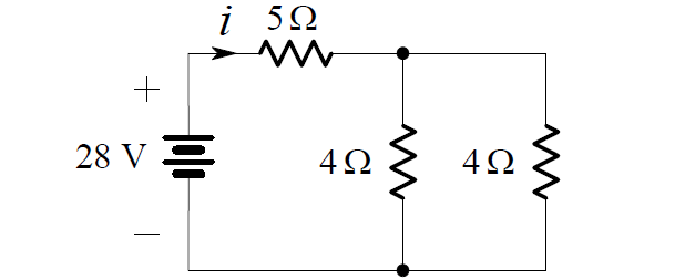
Note that it is not possible to display the original voltage v in this figure. Since the two 4 ohms resistors are connected in parallel, we can further simplify the circuit as shown below:
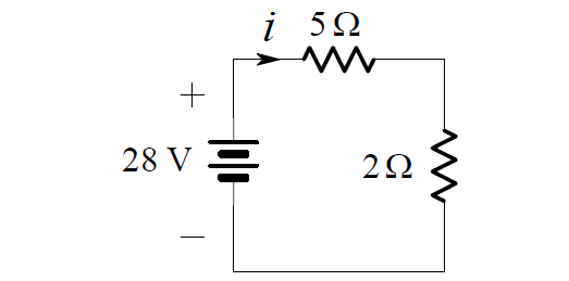
Here, the 5 ohms and 2 ohms resistors are in series, so we may combine them into one 7 ohms resistor.
Then, from Ohm’s Law, we have:
i = 28/7 = 4A