Inst ToolsInst ToolsInst Tools
  • Courses
  • Automation
    • PLC
    • Control System
    • Safety System
    • Communication
    • Fire & Gas System
  • Instrumentation
    • Design
    • Pressure
    • Temperature
    • Flow
    • Level
    • Vibration
    • Analyzer
    • Control Valve
    • Switch
    • Calibration
    • Erection & Commissioning
  • Interview
    • Instrumentation
    • Electrical
    • Electronics
    • Practical
  • Q&A
    • Instrumentation
    • Control System
    • Electrical
    • Electronics
    • Analog Electronics
    • Digital Electronics
    • Power Electronics
    • Microprocessor
  • Request
Search
  • Books
  • Software
  • Projects
  • Process
  • Tools
  • Basics
  • Formula
  • Power Plant
  • Root Cause Analysis
  • Electrical Basics
  • Animation
  • Standards
  • 4-20 mA Course
  • Siemens PLC Course
Reading: Sequential Operation of Output Bits using Two Push buttons
Share
Font ResizerAa
Inst ToolsInst Tools
Font ResizerAa
  • Courses
  • Design
  • PLC
  • Interview
  • Control System
Search
  • Courses
  • Automation
    • PLC
    • Control System
    • Safety System
    • Communication
    • Fire & Gas System
  • Instrumentation
    • Design
    • Pressure
    • Temperature
    • Flow
    • Level
    • Vibration
    • Analyzer
    • Control Valve
    • Switch
    • Calibration
    • Erection & Commissioning
  • Interview
    • Instrumentation
    • Electrical
    • Electronics
    • Practical
  • Q&A
    • Instrumentation
    • Control System
    • Electrical
    • Electronics
    • Analog Electronics
    • Digital Electronics
    • Power Electronics
    • Microprocessor
  • Request
Follow US
All rights reserved. Reproduction in whole or in part without written permission is prohibited.
Inst Tools > Blog > PLC Tutorials > Sequential Operation of Output Bits using Two Push buttons

Sequential Operation of Output Bits using Two Push buttons

Write a PLC program for the sequential operation of output bits using the two push buttons (set and Reset).

Last updated: March 4, 2021 10:50 am
Editorial Staff
PLC Tutorials
No Comments
Share
2 Min Read
SHARE

Write a PLC program so that when the set push button is pressed the first bit in output word is energized and every time the step push button is pressed the next bit is energized till the last bit in the output word, when the reset push button is pressed the output word is reset to zero.

Contents
Inputs & outputsSequential Operation of Output BitsPLC Program

Note: the best practice to learn the PLC programming is to start writing the PLC program, take your time before you review the answer. 

Inputs & outputs

I0.0: set Push Button (Normally open contact)

I0.1: step Push Button (Normally open contact)

I0.2: reset Push Button (Normally open contact)

Qw0: output word i.e from (Q0.0 to Q1.7) 

Sequential Operation of Output Bits
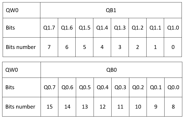
Memory Word order of bits

Before you start your programming you have to understand the order of bits when you hear memory word, here in the table attached you can figure out the address of any bit number.

PLC Program
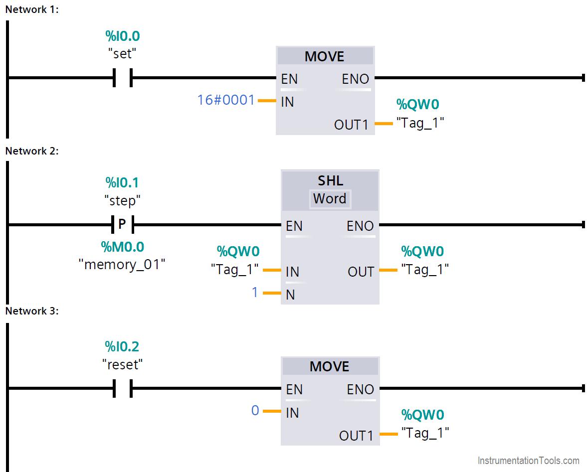
Sequential Operation of Output Bits using Two Push buttons

Network 1

When the set push button is pressed the hexadecimal #0001 is moved to QW0 which is equal to 0000 0000 0000 0001 which will sets the bit Q1.0 to 1.

Network 2

In every time the positive edge of step push button is detected the shift left instruction moves 1 to next bit of the QW0.

Network 3

In any time when the reset push button is pressed, 0 is moved to QW0 which will reset all the output word.

Author: Karim Ali Anwar

If you liked this article, then please subscribe to our YouTube Channel for PLC and SCADA video tutorials.

You can also follow us on Facebook and Twitter to receive daily updates.

Read Next:

  • Masking in PLC
  • ON and OFF Group of Outputs
  • PLC Move Instruction
  • Latching Function of PLC
  • Push button Motor PLC Logic
Don't Miss Our Updates
Be the first to get exclusive content straight to your email.
We promise not to spam you. You can unsubscribe at any time.
Invalid email address
You've successfully subscribed !

Continue Reading

OMRON PLC Tutorial: Car Parking System Application
PLC Problems Troubleshooting
PLC Program for 2 Push buttons to Control 1 Output
What is PLC Redundancy?
Converter Instruction in Siemens PLC Programming
Omron PLC Online Training Course
Share This Article
Facebook Whatsapp Whatsapp LinkedIn Copy Link
Share
Leave a Comment

Leave a Reply Cancel reply

Your email address will not be published. Required fields are marked *

Stay Connected

128.3kFollowersLike
69.1kFollowersFollow
210kSubscribersSubscribe
38kFollowersFollow

Categories

Explore More

Always ON and OFF Bit using Ladder Logic and Statement List
PLC Practice Questions
#9 PLC Best Practices – Validate indirections
Motor Classic Control Circuits using Single Push button
PID Controller Output Types – PID_PWM and PID_Output
Communicating Delta PLC Software to Simulator
Ladder Logic for Control of Double-acting Pneumatic Cylinder
Intrinsically Safe Barriers Questions and Answers

Keep Learning

Traces in TIA Portal

What is Trace Function in Tia Portal?

D flip flop in PLC

D Flip Flop PLC Ladder Logic

Elevator PLC Ladder Logic

Elevator PLC Ladder Logic

Timer-based vacuum cleaner in Schneider PLC

Schneider Electric PLC Timer Problem: Vacuum Cleaner

Single-acting Pneumatic Cylinder operation with Limit Switch

Single-acting Pneumatic Cylinder Operation with Limit Switch

PLC program to control pump

Troubleshooting PLC Permissive Inputs

SCADA Standards

SCADA for Substation Automation

How to Design a Motor Faceplate in Graphics - SCADA Tutorials

How to Design a Motor Faceplate in Graphics? – SCADA Tutorials

Learn More

Process Override Switch

What is Process Override Switch (POS)?

Magnetic Float Level Switch Working Animation

Nuclear Magnetic Resonance Spectrometer Questions and Answers

Sensivity Enhancement for NMR Spectroscopy Questions & Answers

How to identify location of Fire Detectors

How to identify location of Fire Detectors

Technologies for Oxygen Gas Measurement

How to Calibrate Oxygen Analyzer? – O2 Sensor Testing Procedure

Solenoid Valve Failure in Plant Start-Up

Solenoid Valve Failure in Plant Start-Up: Identifying the Root Cause

Relay ladder diagram example

How to Draw a Schematic Diagram ?

PLC Logic for Water Pumping and Chemical Addition

Developing PLC Logic for Water Pumping and Chemical Addition

Menu

  • About
  • Privacy Policy
  • Copyright

Quick Links

  • Learn PLC
  • Helping Hand
  • Part Time Job

YouTube Subscribe

Follow US
All rights reserved. Reproduction in whole or in part without written permission is prohibited.
Welcome Back!

Sign in to your account

Username or Email Address
Password

Lost your password?