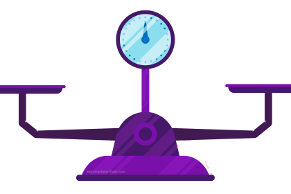
A great many precision instruments use the principle of balance to measure some quantity. Perhaps the simplest example of a balance-based instrument is the common balance-beam scale used to measure mass in a laboratory:
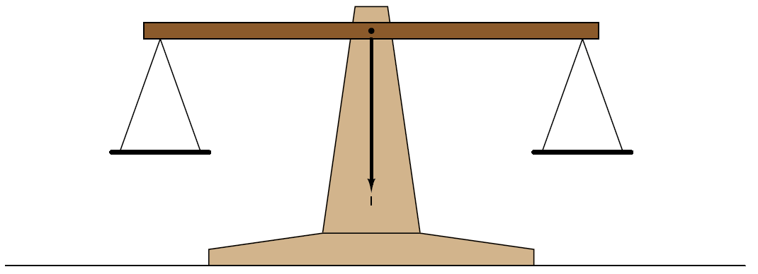
A specimen of unknown mass is placed in one pan of the scale, and precise weights are placed in the other pan until the scale achieves a condition of balance. When balance is achieved, the mass of the specimen is known to be equal to the sum total of mass in the other pan. An interesting detail to note about the scale itself is that it has no need of routine calibration. There is nothing to “drift” out of spec which would cause the scale to read inaccurately. In fact, the scale itself doesn’t even have a gauge to register the mass of the specimen: all it has is a single mark indicating a condition of balance. To express this more precisely, the balance beam scale is actually a differential mass comparison device, and it only needs to be accurate at a single point: zero. In other words, it only has to be correct when it tells you there is zero difference in mass between the specimen and the standard masses piled on the other pan.
The elegance of this mechanism allows it to be quite accurate. The only real limitation to accuracy is the certainty to which we know the masses of the balancing weights.
Imagine being tasked with the challenge of automating this laboratory scale. Suppose we grew weary of employing a lab technician to place standard weights on the scale to balance it for every new measurement, and we decided to find a way for the scale to balance itself. Where would we start? First we would need some sort of mechanism to sense when the scale was out of balance, and another mechanism to apply more or less downward force on the other pan whenever an out-of- balance condition was detected.
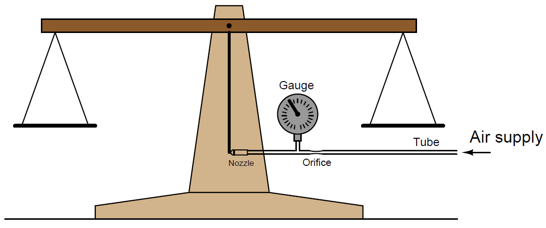
The baffle/nozzle mechanism previously discussed would suffice quite well as a detection mechanism: simply attach a baffle to the end of the pointer on the scale, and attach a nozzle adjacent to the baffle at the “zero” position (where the pointer should come to a rest at balance). Such a mechanism might look like this:
Now we have a highly sensitive means of indicating when the scale is balanced, but we still have not yet achieved full automation. The scale cannot balance itself, at least not yet.
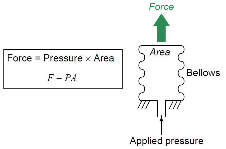
Suppose now instead of using precise, machined, brass weights placed on the other pan to counter the mass of the specimen, we employ a pneumatically-actuated force generator operated by the back-pressure of the nozzle. An example of such a “force generator” is a bellows: a device made of thin sheet metal with circular corrugations in it, such that it resembles the bellows on an accordion. Pneumatic pressure applied to the interior of the bellows causes it to elongate, the amount of force applied to the bellows’ end being the product of air pressure and the end surface area:
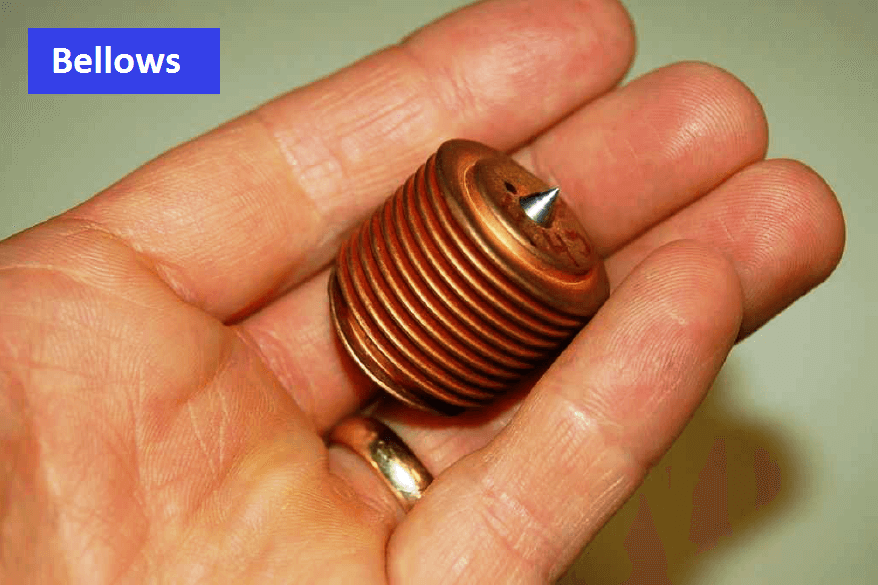
A photograph of a brass bellows unit appears here, taken from a Foxboro model 130 pneumatic controller:
If the bellows’ expansion is externally restrained so it does not stretch appreciably – and therefore the metal never stretches enough to act as a restraining spring – the force exerted by the bellows on that restraining object will exactly equal the pneumatic pressure multiplied by the cross-sectional area of the bellows’ end.
Applying this to the problem of the self-balancing laboratory scale, imagine fixing a bellows to the frame of the scale so it presses downward on the pan where the brass weights normally go, then connecting the bellows to the nozzle back-pressure:
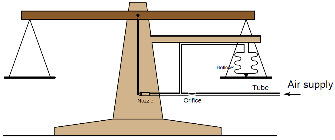
Now the scale will self-balance. When mass is added to the left-hand pan, the pointer (baffle) will move ever so slightly toward the nozzle until enough back-pressure builds up behind the nozzle to make the bellows exert an equal and opposing force to re-balance the mechanism. This balancing action is entirely automatic: the nozzle back-pressure adjusts to whatever value is necessary to maintain the pointer in the balanced position, applying or venting pressure to the bellows as needed to keep the system in a condition of equilibrium. What we have created is a negative feedback system, where the output of the system (nozzle backpressure) continuously adjusts to match and balance the input (the applied weight).
This is all well and good, but how does this help us determine the weight of the specimen in the left-hand pan? What good is this self-balancing scale if we cannot read the balancing force? All we have achieved so far is to make the scale self-balancing. The next step is making the balancing force readable to a human operator.
Before we add the final piece to this automated scale, it is worthwhile to reflect on what has been done so far. By adding the baffle/nozzle and bellows mechanisms to the scale, we have abolished the need for brass weights and instead have substituted air pressure. In effect, the scale translates applied weight into a proportional air pressure: air pressure has now become an analogue for specimen weight. What we really need is a way to now translate that air pressure into a human-readable indication of weight.
To make this air pressure readable to a human operator, all we must add to the system is a pressure gauge. The gauge operates on air pressure, but now the air pressure is proportionately equivalent to specimen weight. In honor of this proportionality, we may label the face of the pressure gauge in units of ounces or grams instead of PSI or kPa:
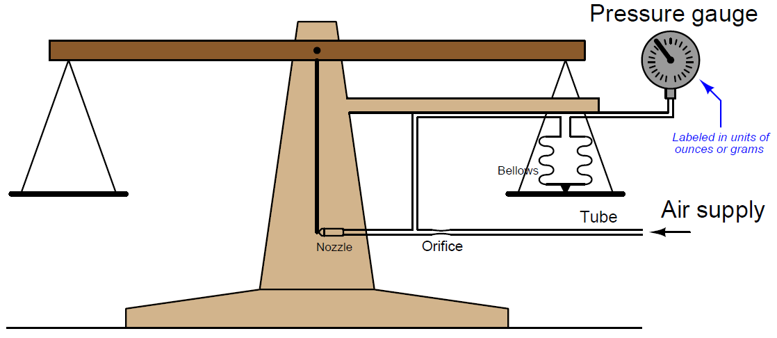
It is very important to note how the pressure gauge performs an entirely different function with the feedback bellows in place. With just a baffle-nozzle mechanism at work, the pressure gauge was hyper-sensitive to any motion of the scale’s balance beam – it served only as a highly sensitive indicator of balance. Now, with the addition of the feedback bellows, the pressure gauge actually indicates how much weight is in the specimen pan, not merely whether the scale is balanced or not. As we add more mass to the specimen pan, the gauge’s indication proportionately increases. As we take away mass from the specimen pan, the gauge’s indication proportionately decreases.
Although it may seem as though we are done with the task of fully automating the laboratory scale, we can go a step further. Building this pneumatic negative-feedback balancing system provides us with a capability the old manually-operated scale never had: remote indication. There is no reason why the indicating gauge must be located near the scale. Nothing prevents us from locating the receiver gauge some distance from the scale, and using long lengths of tubing to connect the two:
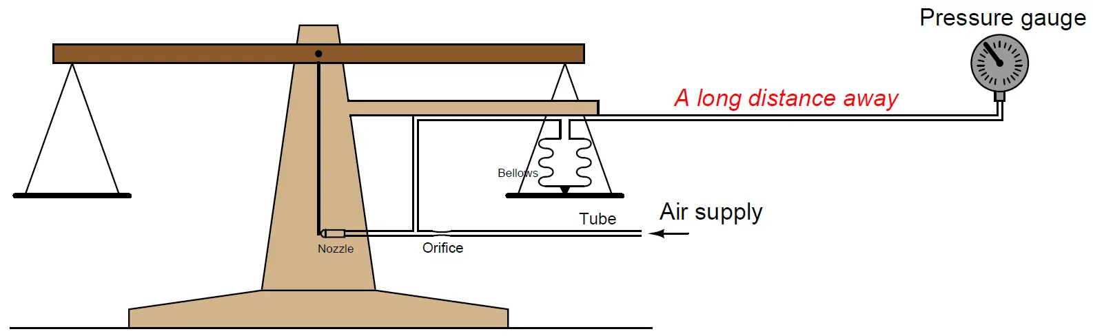
By equipping the scale with a pneumatic self-balancing apparatus, we have turned it into a pneumatic weight transmitter, capable of relaying the weight measurement in analog pneumatic form to an indicating gauge far away. This is the basic force-balance principle used in most pneumatic industrial transmitters to convert some process measurement into a 3-15 PSI pneumatic signal.