The following information is designed to assist in obtaining or providing the necessary information required to select a suitable standard load cell or provide the details required to offer a custom design load cell solution.
There are many factors that determine the suitability of a load cell for a given application or installation:
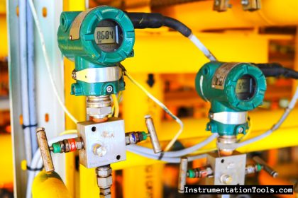
Load Cell
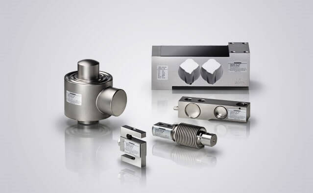
Image Courtesy : siemens
Loading Conditions
- Maximum operating load, force or weight – determine the maximum operating load, force or weight that the load cell will physically see in the application. This will ultimately determine the rated load of the load cell.
- Maximum measurement load, force or weight – determine what the maximum measurement load force or weight that the load cell needs to measure whilst in the application. This may not necessarily be the maximum that it will see during use, and may have an effect on accuracy requirements (discussed later).
- How is the load cell loaded? – determine the way that the load cell is to be loaded i.e. in tension, compression or tension and compression.
- Measurement units – confirm the engineering units that the measurement will be defined in. This may help with instrumentation selection. Some popular options are tonnes (te), kilonewtons (kN), meganewtons (MN), grams (g), kilograms (kg) and pounds (lb), but other specific units can also be considered.
Accuracy
- Accuracy – determine the loading accuracy required for non-linearity and repeatability. This is normally expressed as ±% of full scale output (±%FSO), where full scale output is essentially the rated load of the load cell.
- Thermal errors – for high accuracy applications in wide temperature ranges it may be necessary to temperature compensate a load cell. Determine the thermal errors required. This is normally expressed as ±% full scale output per ˚C or ˚F (±%FSO/˚C or ±%FSO/˚F).
Adverse Loading Conditions
- Overloading conditions – will the applied load ever exceed the maximum load? If so, by how much? This will determine the overload capacity required and to what level we will need to proof load the load cell to.
- Overloading capacity – are there any additional safety factors that need to be considered for the application? This will determine the overload capacity required and to what level we will need to proof load the load cell to.
- Dynamic loads – are there any dynamic loads involved in the application? High dynamics within the normal working range of the load cell may cause an overload condition. Obtain details of the velocity, magnitude and frequency of the dynamic loads, so that this can be considered in the rating of the load cell or its overload capacity.
- Fatigue loading – fatigue loading can occur when continuous cyclic loading is applied to the load cell. This may determine the rating and design of the load cell. Obtain details of the load level that is being applied for each cycle, the frequency of the cycle and the total number of cycles the load cell will see during its working life. A fatigue rated load cell may be required.
- Off-axis loading – In some applications the load may not be applied constantly through the principle design axis of the load cell. This may affect the accuracy or potentially damage the load cell. There may be certain load cells that can resist this, or accessories that can eliminate them from the load cell i.e. load buttons, rod end bearings. Try to obtain installation drawings which will show where the load cell is installed, so we can suggest any possible solutions.
Mechanical Requirements
- Size constraints – are there any issues with space in the application that means that the load cell has to be a certain size to fit? i.e. maximum dimension requirements exist, or are certain dimensions required to fit or attach the load cell?
- Limited access – is there limited access to where the load cell is to be installed that would affect the type of load cell that needs to be selected to enable practical and economical installation?
- Mounting configuration – is a particular style of load cell required for the application? Popular styles include:
- column compression load cells
- low profile compression load cells
- miniature compression load cells
- low profile pancake load cells
- beam load cells
- threaded tension and compression load cells
- S Type load cells
- load links
- Load shackles
- Load pins
Mounting Attachment
- Attachment options – there are various ways that a load cell could be installed/attached in an application and which may influence the load cell choice. In addition to any customer specific requirements, these may include:
- threaded joints
- clevis pin
- flange mounting
- load buttons
- clevis tongue
- linkage hole
- pulley bearing
Electrical Considerations
- Signal output – there are various options available for all load cells. Where space allows it is possible to have the signal conditioning built into the load cells. Where space is not available, external instrumentation can be offered (please see separate data sheet “How to select an instrument”). Some examples of internal/built-in signal conditioners include:
- Analogue
- mV/V (standard bridge output)
- 0-5vdc
- 0-10vdc
- +/- 10vdc
- 2-wire 4-20mA
- 3-wire 4-20mA
- Digital
- RS485, ASCII
- RS485, Mantrabus
- RS485, Modbus
- MantraCAN
- TEDS
- Wireless
- wireless associated products
- Analogue
Electrical connection methods
There are various methods of obtaining connections from the load cell to the outside world. These will depend on the customers’ requirements and will be affected by the environmental conditions that the load cell is used in.
- Integral connector and mating cable assembly – environmental sealing and installation condition details will be required to select a suitable connector
- Integral glanded cable – the cable is hardwired to the load cell through a cable gland
- Hose protected cable exit – the cable may require hose protection to prevent mechanical wear or to limit attack from animals or environmental conditions
- Position of cable exit – the cable exit may need to exit from a certain position on the load cell for installation reasons.
Environmental Considerations
- Operating temperature range – what are the minimum and maximum temperatures that the load cell will be operating in?
- Storage temperature range – what are the minimum and maximum temperatures the load cell will be stored in?
- Environmental noise – will the load cell be exposed to noise levels that will cause vibration?
- IP/NEMA rating (environmental sealing) – what level of environmental sealing is required?
- Hazardous Area (ATEX/IECx) – minimum zone rating required, ATEX or IECx certification
- Indoor or outdoor use – level of sealing required for water and/or dust ingress. Will the load cell be submerged, to what depth and what will it be submerged in? Is any additional mechanical protection required once installed?
Article Source : .lcmsystems