The Seebeck effect is one of the three major variations, which can be observed under thermoelectric effect. It was named after the German physicist Thomas Johann Seebeck, who discovered the phenomena of thermoelectric effect during his independent research in 1821.
The conversion of the temperature difference between two non-similar electrical conductors or semiconductors directly into electric potential is known as thermoelectric effect. When these conductors with a difference in potential are brought in contact using an electrical connection, it results in the flow of charged particles that generate a current flow. The reverse case is also applicable where an application of potential difference to the two dissimilar electrical conductors will give rise to a difference in temperature at their junction.
Seebeck Effect Theory
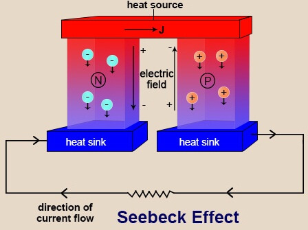
In the Seebeck effect, the same phenomena occurs, and there is a generation of electrical potential due to the application of a heat source. This electric potential can be measured across the ‘hot’ and the ‘cold’ ends of the junction.
Consider two semiconductors, n-type and p-type, connected to a common source of heat supply, which raises the temperature of the connected end. The other ends of these two semiconductors are at a relatively low temperature, and a thermal gradient results. The electrons at the ‘hot’ end of the n-type conductor receive the thermal energy from the source. They get energized and flow towards the ‘cold’ end. In this manner, the hot end has low density of charge carriers (electrons for n-type and holes for p-type), whereas the cold end has a higher density of charge carriers. This distribution of charges builds an electric field across the junction. When a conductor is used to connect the two ends of the junction, charges begin to flow through it, and electric current is produced.
There are three forms in which the Seebeck effect maybe observed.
- Connecting a load across the two ends will power up the load, and the two materials along with the heat source will act as the generator.
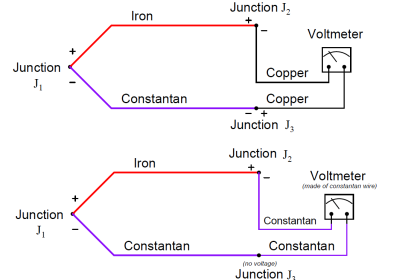
- If a voltmeter is connected to the two ends using a conductor, the voltage measured can be used to determine the temperature difference between the two ends.
- Another most common connection is using the setup as a switch to yet another electrical setup or circuit, and hence, controlling its operation.
Seebeck Generator
The combination of two dissimilar conductors connected to a heat supply and converting it into voltage to power the load demand is called a Seebeck generator. It can be used to generate electricity to power low-scale load requirements independently, i.e., without any external source of electricity connected to it. The heat flow from the higher temperature portion of the junction to the relatively cooler parts of the conductor results in a thermal gradient and resultant heat flow. The constituent particles of the junction get charged and begin to move from higher density area to lower density area. The resulting voltage difference due to flow of charges behaves as the power source for the connected load. With no rotating parts involved, these find applications in low-power remote installations.
It is known that the voltage generated across the conductors is directly proportional to the temperature gradient across them. The constant of proportionality is called thermopower or Seebeck coefficient. In other words, the rate of change of temperature difference to the corresponding rate of change in the voltage produced is related by the Seebeck coefficient.
Mathematically,
V = – S(Th – Tl)
where, V = Potential difference
S = Seebeck coefficient
Th = Temperature at hot end
Tl = Temperature at cold end
or,
δV = – S (δT)
where, δV = change in voltage
δT = change in temperature difference
The Seebeck coefficient is in its standard form, and is defined as the amount of voltage produced between two conductors when the temperature across them is sustained at 1 Kelvin throughout the observation, i.e.,
Applications of Seebeck Effect:
There are a variety of mechanical and chemical properties that vary with the change in temperature. Therefore, Seebeck effect when used for monitoring the net change in temperature using the achieved electrical potential can be useful to study or determine those parameters as well. These include the testing of material strength, degradation, and radiation strength from radioactive elements that change with temperature over the period of time. The resulting electrical signals from these thermoelectric devices can be used to actuate safety switches or alarms in order to signal the condition.
Thermocouples – This thermoelectric device is a combination of at least two different conductors or semiconductors used for measuring the temperature difference or the temperature rise by converting the resultant electrical parameter into its corresponding temperature. It may be used to initiate circuits or valves as well.
Thermopiles – Thermopiles are a number of thermocouples connected in series (sometimes parallel) to obtain usable voltage to supply relatively higher scale power requirements.
High-frequency power sensors – Seebeck effect has been found useful in finding the accurate amplitude of sinusoidal waves. This has helped detect the presence of hyperfrequency power generated in a system and signal the operators.
Power generators – Cogeneration using Seebeck effect has been proposed and applied by many power generating units to utilize the waste heat generated in the industry to produce additional power.
Spin Seebeck Effect
Modern scientists have been able to provide another dimension to the study of Seebeck effect by studying the effect of application of heat supply to magnetized electrical conductors. The charge carriers, driven by the thermal gradient, reposition themselves in accordance to their individual spin or angular momentum. This phenomenon was discovered recently in 2008. Contrary to the convention, there is no wastage of heat during the rearrangement of particles. This effect is widely applied to make fast-response micro switches.
The recent developments in this area have led researchers to try developing power sources that use both solar and thermoelectric cells to increase the combined efficiency of the two cells, with solar radiations as the source of heat.
Also Read: Thermistor Working Principle