In this article, you will learn the Schneider PLC programming example for beginners based on input switches and output motors.
Note: The PLC problem statement below is aimed at the freshers and students to understand the ladder logic.
Schneider PLC Programming Example
Problem Statement
Design a PLC ladder logic for the following application.
There is a use of four toggle switches to control four motors.
If Switch 1 is ON, then Motor I and Motor II will be ON.
If Switch 2 is ON, then Motor II and Motor III will be ON.
If Switch 3 is ON, then Motor III and Motor IV will be ON.
If Switch 4 is ON, then Motor I and Motor IV will be ON.
PLC Program

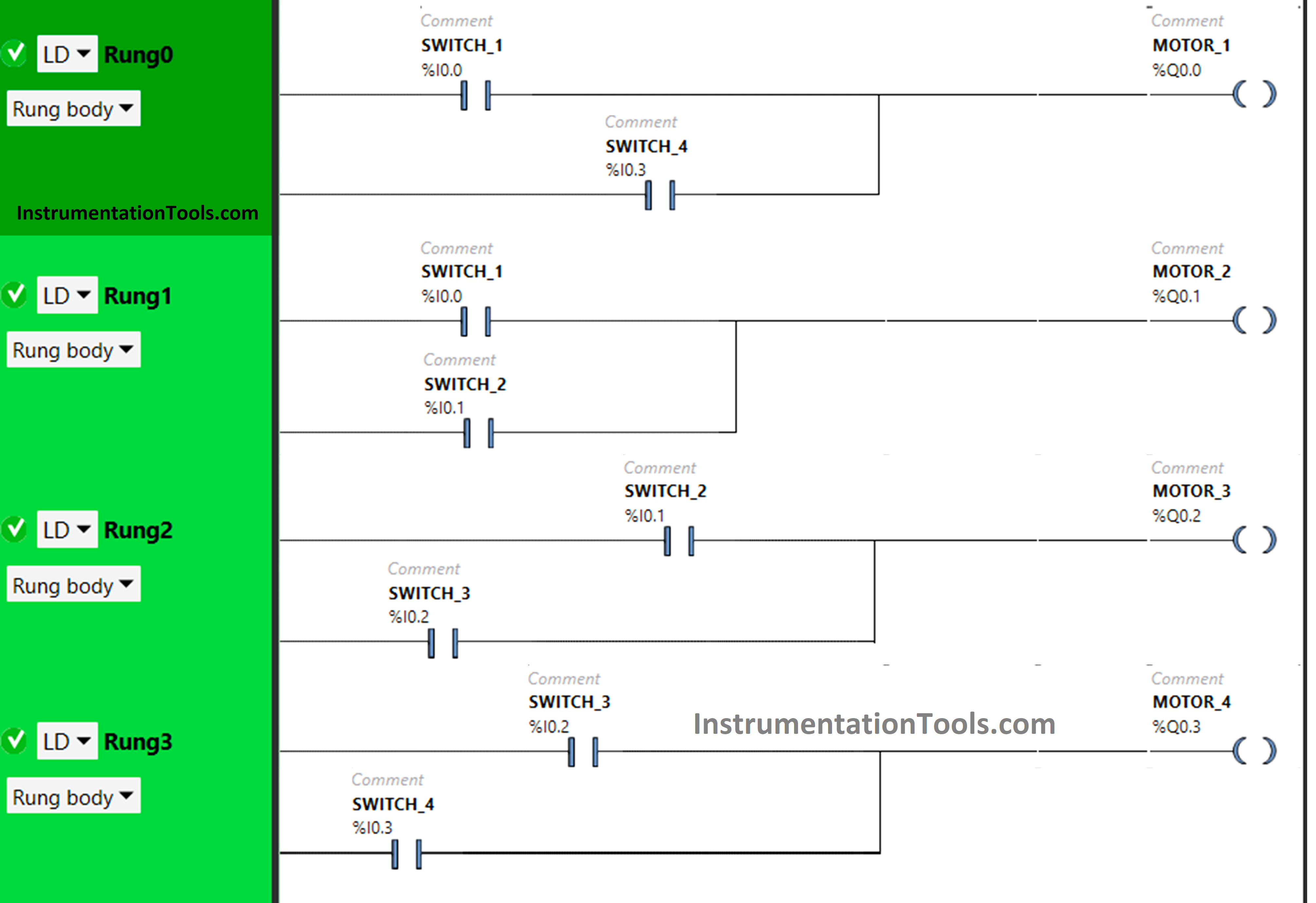
I/O List
Digital Inputs:
The required inputs are listed below.
- Switch 1: I0.0
- Switch 2: I0.1
- Switch 3: I0.2
- Switch 4: I0.3
Digital Outputs:
The required outputs are listed below.
- Motor 1: Q0.0
- Motor 2: Q0.1
- Motor 3: Q0.2
- Motor 4: Q0.3
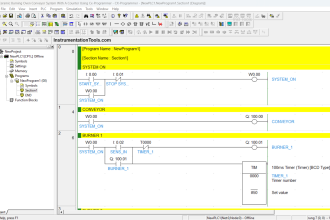
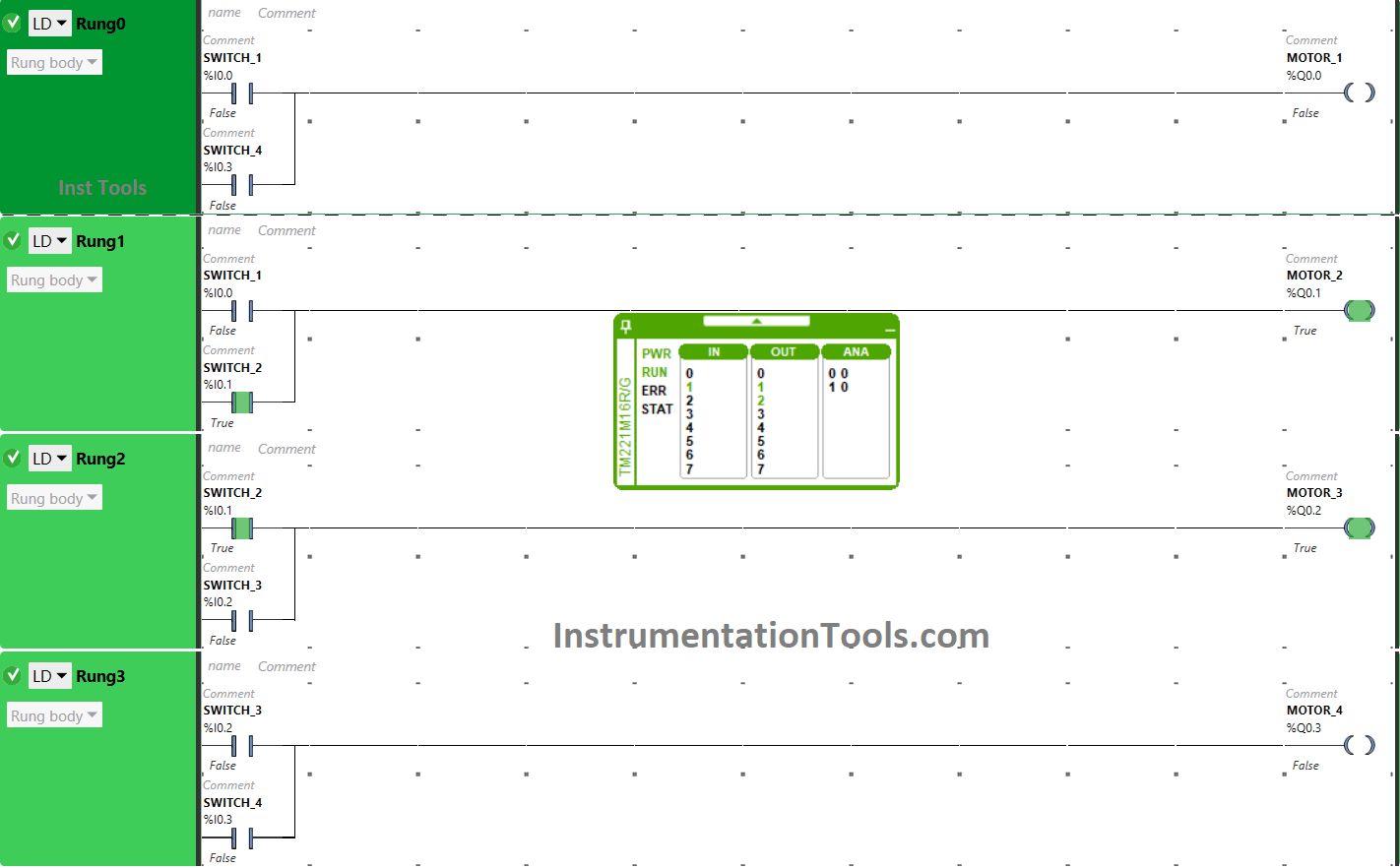
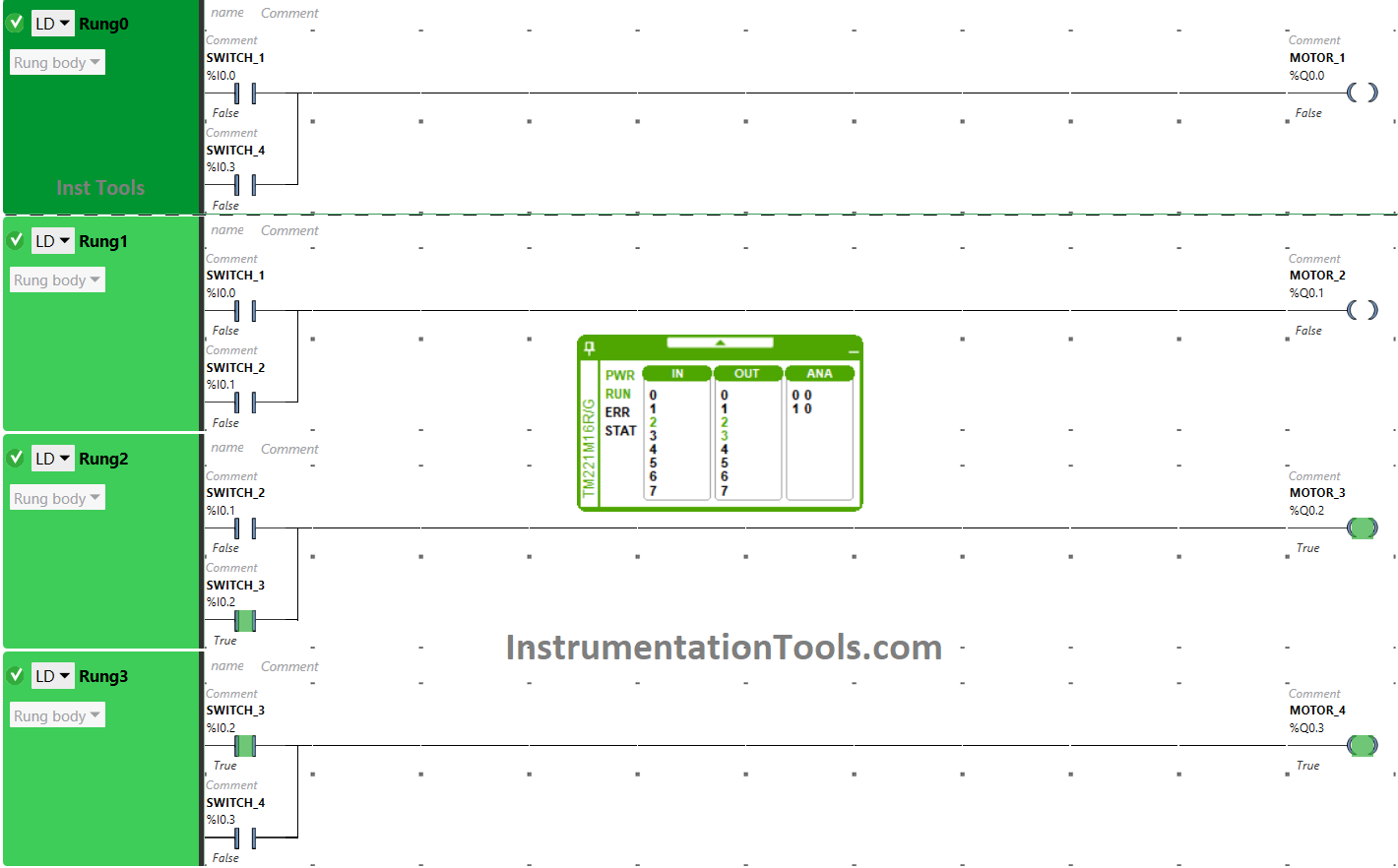
PLC Programming Example for Beginners
Logic Explained
Here in this program, we used EcoStruxure Machine Expert Basic PLC software.
In the above program, we have used Normally Open Contact for Switch 1 (I0.0), Switch 2 (I0.1), Switch 3 (I0.2), and Switch 4 (I0.3)
Switch 1 and Switch 4 are connected in parallel for Motor 1, thus implementing OR logic gate.
For Motor 2, inputs switch 1 and switch 2 are connected in parallel, thus implementing OR logic gate.
Switch 2 and switch 3 are implementing OR logic gate i.e., connected in parallel for Motor 3.
Switch 3 and Switch 4 are connected to Motor 4 in parallel to implement OR logic gate.
For Motor 1 to be ON, either Switch 1 or Switch 4 should be ON.
To turn ON Motor 2, either Switch 1 or Switch 2 should be ON.
When Switch 2 or Switch 3 is ON, then Motor 3 will turn ON.
Motor 4 will turn ON when Switch 3 or Switch 4 is turned ON.
PLC Program Analysis
Now we will see the above PLC program result analysis with different input combinations.
When Switch 1 is ON
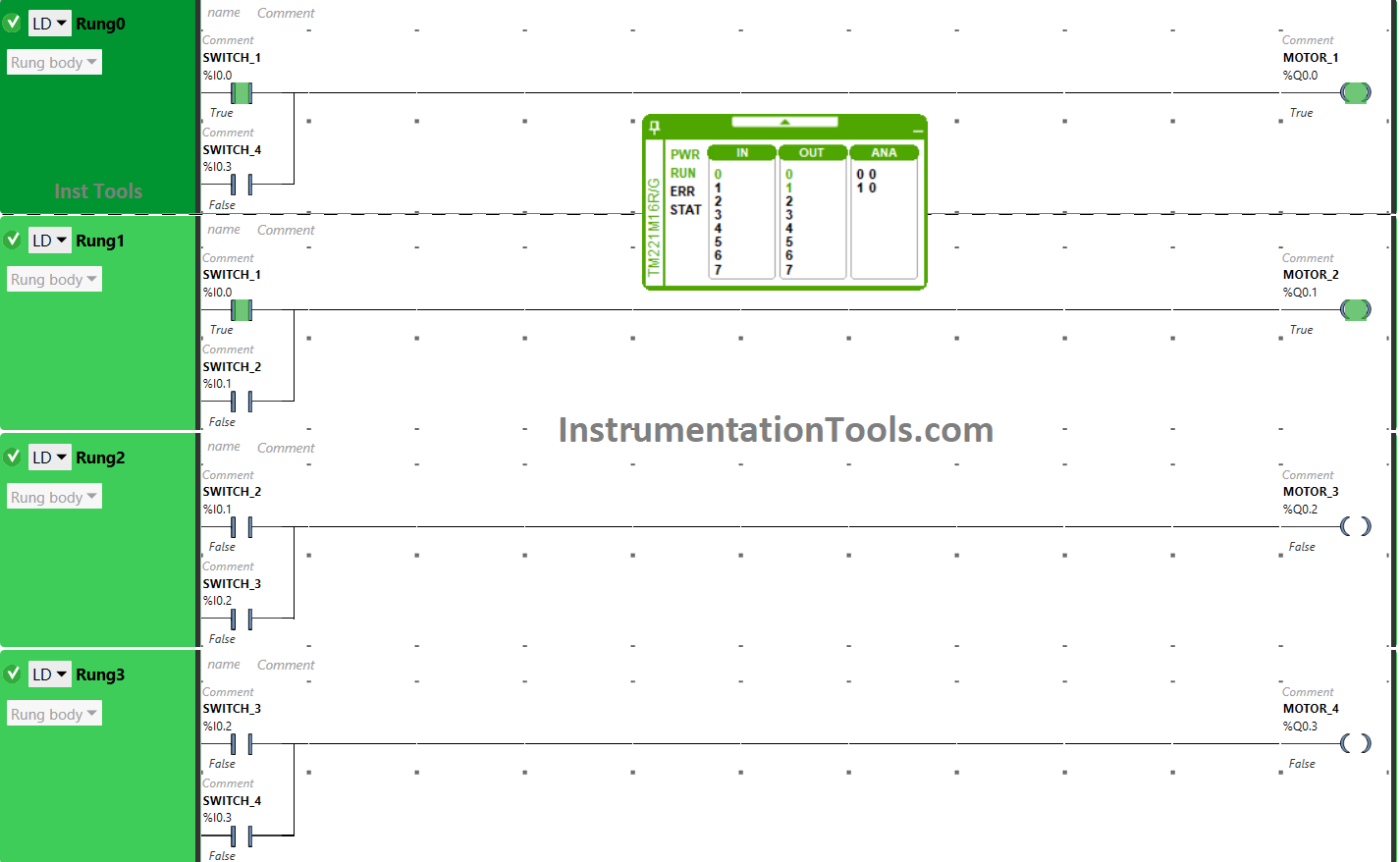
When toggle switch 1 is turned ON, the signal flows through it. As a result, Motor 1 and Motor 2 get ON.
Other motors will remain OFF because Switch 1 is not connected to them.
When Switch 2 is ON
The signal will flow through switch 2 when it is turned ON that will turn ON Motor 2 and Motor 3. It is so because switch 2 is connected to Motor 2 and Motor 3 only.
When Switch 3 is ON
When Switch 3 is turned ON, the signal flows through it that will turn Motor and Motor 4 ON. The input switch 3 is connected to these outputs only.
Motor 1 and Motor 2 will remain OFF as Switch 3 is not connected to them.
When Switch 4 is ON
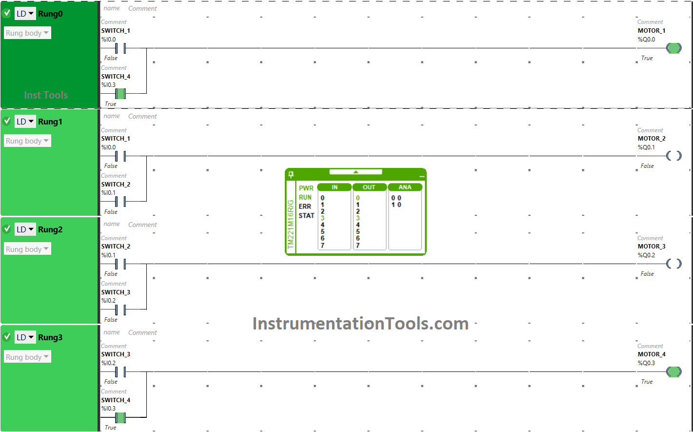
Switch 4 will turn ON Motor 1 and Motor 4 when turned ON. Switch 4 is connected to these motors only but on with Motor 2 and Motor 3.
If you liked this article, then please subscribe to our YouTube Channel for PLC and SCADA video tutorials.
You can also follow us on Facebook and Twitter to receive daily updates.
Read Next:
- Siemens Control System (TDC)
- PLC Tag Naming Conventions
- Electrical Diagram into PLC Program
- Control Algorithms in PLC Programming
- PLC Example to Control LEDs Via Switches