Very basic does not imply obvious…i really like this statement. Very often the answer is very fundamental and basic to us, somehow it always does not obvious to us.
Restriction Orifice after Blowdown valve
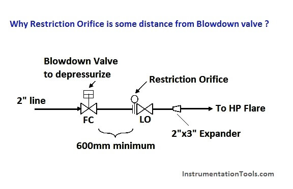
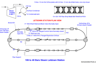
Lets look at the above sketch. It is a typical arrangement for a Blowdown Valve (BDV) with Restriction Orifice (RO) , located downstream of the Blowdown valve. This arrangement typically used to depressurized a system inventory to a safe level within a limited time to minimized catastrophic scenario. Between the Blowdown valve and Restriction orifice, there 600 mm spool piece between them.
What the main purpose of this 600mm spool piece ?
Is this spool for straightening and smooth flow ?
Is this spool to avoid secondary choke ?
Guess what ?
Reasoning…Major pressure drop will take place at Restriction Orifice, downstream of Blowdown valve during blowdown. Joule-Thompson (JT) effect results fluid temperature downstream of Restriction Orifice drops below subzero (Less than zero degree Celsius). Latent heat in the piping will transfer to cold fluid and slowly approaching this subzero temperature. The “coldness” will travel back to upstream of Restriction orifice and probably reaches Blowdown valve.
It potentially cause the upstream Blowdown valve body temperature drops below subzero as well. Moisture from atmosphere will freeze at the Blowdown valve body and potentially cause the stem stuck at position. Operator may not possible to close the Blowdown valve after blowdown activities and may potentially lead to back flow. Those “general good engineering practice is to locate Restriction orifice, 600mm downstream of Blowdown valve.
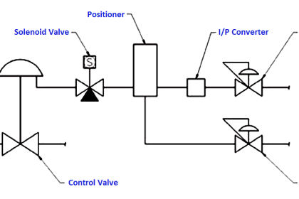






The failure position of the BDV in the diagram should be FO not FC. A FC valve will prevent blowdown on instrument air failure if it happens when there is a demand for blowdown. This will lead to a catastrophic condition developing.
why is the BDV not a fail to open(FO)type?
BDV should be Fail to Open not Fail to Close
very important subject.