Resistance Temperature Detectors (RTD) Sources of Error
Immersion Error – Stem Conduction
With the calibration of industrial platinum resistance thermometers (RTD) stem conduction is likely to be the main source of error.
Immersion or Stem Conduction errors are caused by the flow of heat along the thermometer sheath. If the thermometer is immersed into a hot body the flow of heat will be from the body along the thermometer sheath into the ambient surroundings. Conversely if the thermometer is placed into a body cooler than the surroundings then heat will flow along the sheath into the cool body. The temperature profile along the stem can lead to errors.
The below Figure shows a thermometer with an internal sensing element of 20mm. The thermometer is immersed only 10mm and it is clear that the thermometer will not be able to reach the temperature of the body. The important question is, how far should the thermometer be immersed to eliminate the immersion error? This will depend on various factors including the characteristics of the thermometer and the temperature difference between the stem and the body of interest.
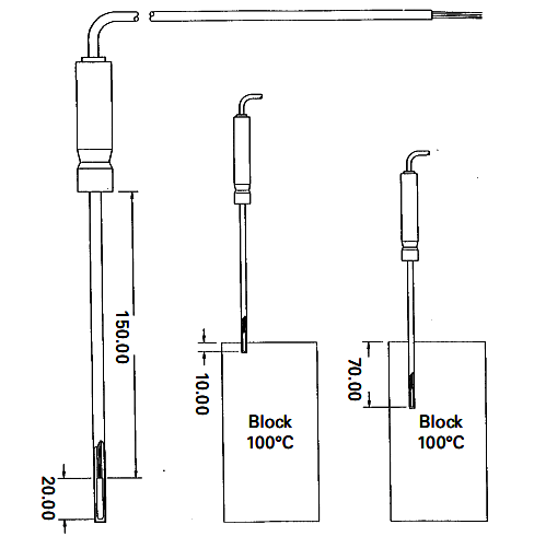
Various methods or mathematical models have been suggested to allow this error to be calculated but the number of variables involved make it difficult in practice to calculate the error. From the practical point of view it may be better to immerse the thermometer as much as possible and to experiment by withdrawing the thermometer and observing any effect. It has been suggested that for metal block baths as a rule of thumb a thermometer should be inserted into the block the length of the detector plus an amount equal to 15 times the thermometer’s diameter.
For calibration of industrial P.R.T.’s in metal block baths this is likely to be the dominant source of error and will influence the uncertainty of calibration.
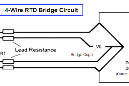
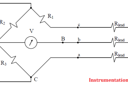
Lead Resistance
Resistance thermometers are, in a sense all “two wire” devices. It is when extension wires are attached to the sensing resistor that complete thermometers can become two wire, three wire or four wire connected.
Two wire devices are best avoided whenever possible. The extension wire becomes part of the thermometer and as the lead length becomes greater so does the lead resistance error.
Three wire devices can be used to largely overcome errors introduced by the extension wires. Such devices can easily be connected to electrical circuits such that the lead wire resistances cancel each other. However slight errors remain due to variations in the resistance of the individual wires.
Four-wire connection offers further improvements but industrial instruments do not always have input connections designed for four-wire connection, although laboratory instruments commonly do.
Thermal Lag
Errors due to thermal lag are those caused by the delay in the thermometer to respond to a change in temperature. Again mathematical models exist for this effect but in practice the time constant for industrial thermometers is often unknown.
For a thermometer which is in a close fitting pocket of a metal block bath (which exhibits good temperature stability) it would be usual for the thermometer to reach its final value within a few minutes. A simple observation is the best means to confirm this for new or unknown sensors.
Thermal Capacity
When a thermometer is placed into a metal block bath, heat will flow into the thermometer, or from it. This loading of the block may cause the block to change its temperature, although the temperature controller of the block will compensate to some extent.
With Standard block baths and the recommended method of using an external thermometer to measure the insert temperature such errors can be kept to a minimum. Ideally the thermal capacity of the block bath should be large compared to the thermal capacity of the probe, which will be the case for all but the largest of industrial probes.
Self Heating
Measuring the resistance of a p.r.t. requires an electrical current to be passed through the sensing resistor. The resultant power dissipated in the sensor (I2R) is often warned against. In practice, for industrial probes with modern instrumentation, it is unlikely to cause significant error.
The traditional Temperature Calibration Using Dry Block Baths 13 measuring current has been 1mA but modern instruments tend to use much smaller values that minimise any self heating, but may lead to other more significant DC errors. Users of laboratory standard platinum resistance thermometers need take more care to eliminate self heating errors.
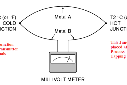
DC Errors
Small D.C. voltages may be generated in p.r.t.’s due to thermoelectric effects caused by the joining of dissimilar metals in the construction of the p.r.t. For example the junction of copper to platinum can generate e.m.f. of 6 to 8 µV /ºC. Resulting offset voltages can lead to error in associated instrumentation although laboratory instruments may use measuring techniques to eliminate such errors.


Excellent Information for anyone working with RTD”S .I recommend the use of heat transfer paste always inside a pocket and the surface of the RTD. Self heating effect on cheap probes can be an issue there are higher quality probes that are available which do not get effected as much by this.They come in different Grades eg A B or C.I recommend that after you do a loop calibration, always connect the RTD to circuit and do an actual temperature check with a known standard thermometer verses the RTD to see if there is an error, as the loop Calibration might need a slight zero shift to get everything correct.