Electromechanical relays may be connected together to perform logic and control functions, acting as logic elements much like digital gates (AND, OR, etc.).
A very common form of schematic diagram showing the interconnection of relays to perform these functions is called a ladder diagram. In a “ladder” diagram, the two poles of the power source are drawn as vertical rails of a ladder, with horizontal “rungs” showing the switch contacts, relay contacts, relay coils, and final control elements (lamps, solenoid coils, motors) drawn in between the power rails.
Ladder diagrams differ from regular schematic diagrams of the sort common to electronics technicians primarily in the strict orientation of the wiring: vertical power “rails” and horizontal control “rungs.”
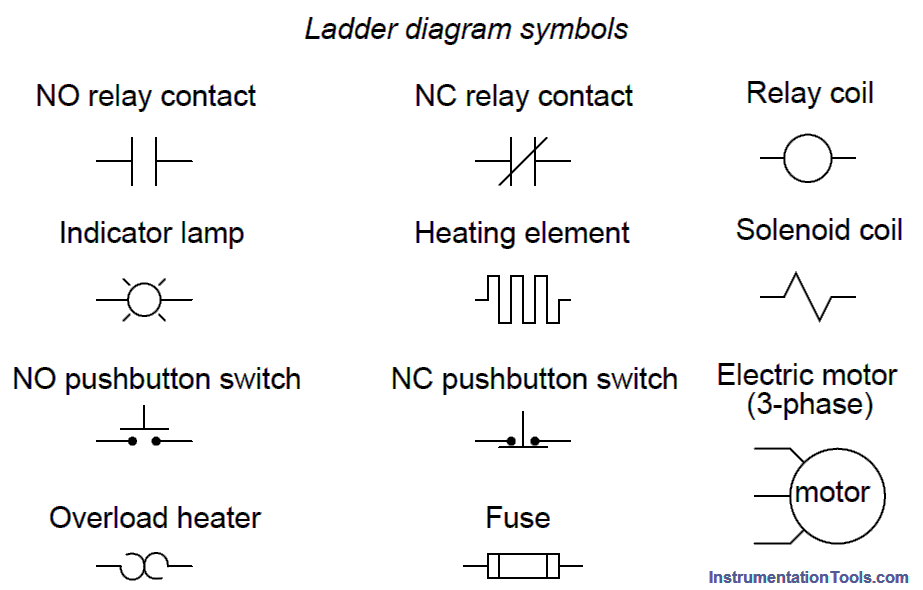
Symbols also differ a bit from common electronics notation: relay coils are drawn as circles, with relay contacts drawn in a way resembling capacitors:
Unlike schematic diagrams where the association between relay coils and relay contacts is represented by dashed lines, ladder diagrams associate coils and contacts by label.
Sometimes you will find relay contacts labeled identically to the coil (e.g. coil labeled CR5 and all contacts for that relay also labeled CR5) while other times you will find suffix numbers used to distinguish individual contacts within each relay from each other (e.g. coil labeled CR5 and its three contacts labeled CR5-1, CR5-2, and CR5-3).
Another notable convention in relay circuits and their ladder diagrams is that each and every wire in the circuit is labeled with a number corresponding to common connection points.
That is, wires connected together always bear the same number: the common number designates a condition of electrical commonality (all points bearing the same number are equipotential to each other).
Wire numbers only change when the connection passes through a switch or other device capable of dropping voltage.
Perhaps the most confusing aspect of relay control circuits is to grasp is the meaning of normal as it applies to the status of relay contacts. As discussed previously, the word “normal” in this context – whether it be the status of hand switches, process switches, or the switch contacts inside control relays – means “in a condition of rest” or no stimulation.
In other words, a “normally open” relay contact is open when the relay coil is unpowered and closed when the relay coil is powered. Likewise, a “normally-closed” relay contact is closed when the relay coil is unpowered and open when the relay coil is powered.
To illustrate this concept, let us examine a relay control circuit where a pressure switch activates an alarm light:
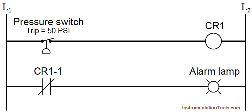
Here, both the pressure switch and the relay contact (CR1-1) are drawn as normally-closed switch contacts. This means the pressure switch contact will be closed when the applied pressure is less than its trip point (50 PSI), and the relay switch contact will be closed when the relay coil is de-energized.
When analyzing the operation of a relay control system, it is helpful to have some way to temporarily denote the conductive status of switch contacts and the energization status of relay coils (i.e. a notation we might sketch using pencil on a diagram to help us follow the operation of the circuit).
A symbology I recommend is the use of arrow and “X” symbols to represent power flow and no power flow (respectively). These symbols clearly denote component status while avoiding confusion with the symbols used to denote normal status of switch contacts.
In this next diagram, we assume the applied pressure is less than 50 PSI, leaving the pressure switch in its “normal” (closed) state:
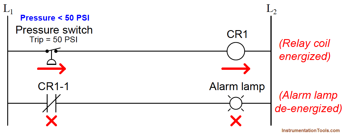 Since the pressure is insufficient to actuate the pressure switch, its contact remains in the “normal” state (closed). This sends power to relay coil CR1, thus actuating contact CR1-1 and holding it in the open state. With CR1-1 contact open, the alarm lamp receives no power. In this example we see the pressure switch in its “normal” state but the relay in the actuated state.
Using arrow and “X” symbols again to represent the presence or absence of power in this circuit, we will now analyze its status with an applied switch pressure greater than 50 PSI:
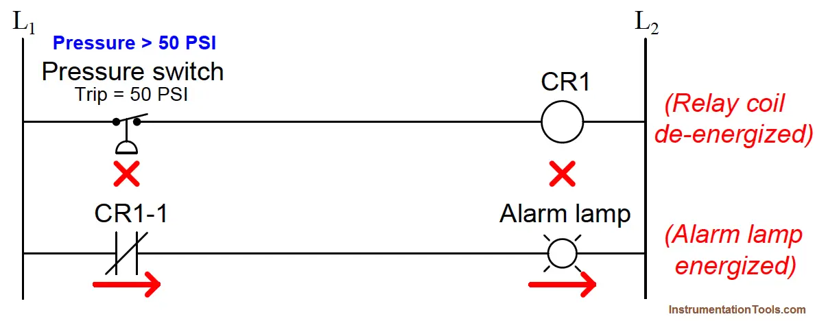
Now that there is sufficient fluid pressure applied to the switch to actuate it, its contact is forced into the actuated state which for this “normally-closed” switch is open.
This open condition deenergizes relay coil CR1, allowing relay contact CR1-1 to spring-return to its normal status (closed), thus sending power to the alarm lamp. From this analysis we see that the lamp fulfills the function of a high pressure alarm, energizing when the applied pressure exceeds the trip point.
Where we typically find themselves confused is assuming the switch contact will be in the same state it is drawn in. This is not necessarily true.
The way switch contacts are drawn merely reflects their normal status as defined by the switch manufacturer, which means the status of the switch when there is no (or insufficient) actuating stimulus present.
Whether or not the switch will actually be in its normal state at any given time is a question of whether or not a sufficient stimulus is present to actuate that switch.
Just because a switch is drawn normally-closed does not necessarily mean it will be closed when you go to analyze it. All it means is that the switch will be closed when nothing actuates it.
This exact same principle applies to relay ladder-logic programming in electronic control systems called PLCs (Programmable Logic Controllers).
In a PLC, a digital microprocessor performs the logic functions traditionally provided by electromechanical relays, with the programming for this microprocessor taking the form of a relay diagram (also called a “ladder-logic” diagram).
we will discuss the same concept using PLC ladder logic.