Air compressors of various designs are used widely in numerous applications. Compressed air has numerous uses throughout a facility including the operation of equipment and portable tools.
Three types of designs include
The reciprocating air compressor, illustrated in Figure 1, is the most common design employed today.
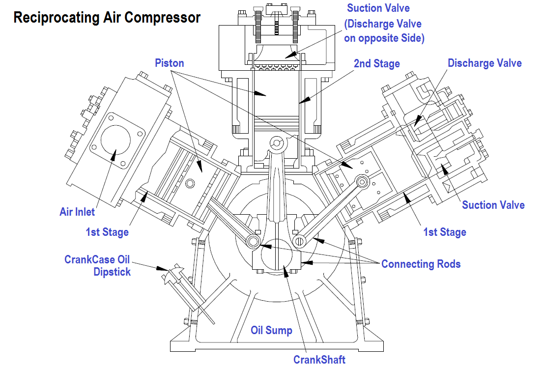
Figure 1 Reciprocating Air Compressor
The reciprocating compressor normally consists of the following elements.
A section of a typical reciprocating single-stage, single-acting compressor cylinder is shown in Figure 2. Inlet and discharge valves are located in the clearance space and connected through ports in the cylinder head to the inlet and discharge connections.
Figure 2 : Single-Acting Air Compressor Cylinder
During the suction stroke the compressor piston starts its downward stroke and the air under pressure in the clearance space rapidly expands until the pressure falls below that on the opposite side of the inlet valve (Figures 2B and 2C). This difference in pressure causes the inlet valve to open into the cylinder until the piston reaches the bottom of its stroke (Figure 2C).
During the compression stroke the piston starts upward, compression begins, and at point D has reached the same pressure as the compressor intake. The spring-loaded inlet valve then closes. As the piston continues upward, air is compressed until the pressure in the cylinder becomes great enough to open the discharge valve against the pressure of the valve springs and the pressure of the discharge line (Figure 2E). From this point, to the end of the stroke (Figures 2E and 2A), the air compressed within the cylinder is discharged at practically constant pressure.
Learn the example of flip-flop PLC program for lamps application using the ladder logic to…
In this article, you will learn the STAR DELTA programming using PLC controller to start…
Lube oil consoles of rotary equipment packages in industrial process plants are usually equipped with…
Rotating equipment packages such as pumps, compressors, turbines need the lube oil consoles for their…
This article explains how to blink lights in ladder logic with a detailed explanation video…
In this article, a simple example will teach you the conversion from Boolean algebra to…

