Inst ToolsInst ToolsInst Tools
  • Ask
  • Courses
  • Videos
  • Q & A
    • Interview
      • Instrumentation
      • Electronics
      • Electrical
      • Practical Questions
    • MCQ
      • Instrumentation MCQ
      • Electrical MCQ
      • Electronics MCQ
      • Control Systems MCQ
      • Analog Electronics MCQ
      • Digital Electronics MCQ
      • Power Electronics MCQ
      • Microprocessor MCQ
      • Multiple Choice Questions
  • EE
    • Electronics
      • Electronics Q & A
      • Electronic Basics
      • Electronic Devices & Circuits
      • Electronics Animation
      • Digital Electronics
    • Electrical
      • Electrical Basics
      • Electrical Q & A
      • Power Electronics
      • Electrical Machines
      • Electrical Animation
      • Power Systems
      • Switchgear & Protection
      • Transmission & Distribution
  • Measure
    • Control Valves
    • Calibration
    • Temperature
    • Pressure
    • Flow
    • Level
    • Analyzers
    • Switches
    • Vibration
    • Solenoid Valve
  • Control
    • PLC Tutorials
    • Control Systems
    • Safety Instrumented System (SIS)
    • Communication
    • Fire & Gas System
  • More
    • Design
    • Tools
    • Animation
    • Basics
    • Formulas
    • Standards
    • TextBooks
    • Common
    • Software
    • Excel Tools
    • Erection & Commissioning
    • Process Fundamentals
    • Videos
    • Books
Search
All rights reserved. Reproduction in whole or in part without written permission is prohibited.
Reading: Pull Up and Pull Down Switch Circuits
Share
Notification Show More
Font ResizerAa
Inst ToolsInst Tools
Font ResizerAa
  • Courses
  • PLC Tutorials
  • Control Systems
Search
  • Ask
  • Courses
  • Videos
  • Q & A
    • Interview
    • MCQ
  • EE
    • Electronics
    • Electrical
  • Measure
    • Control Valves
    • Calibration
    • Temperature
    • Pressure
    • Flow
    • Level
    • Analyzers
    • Switches
    • Vibration
    • Solenoid Valve
  • Control
    • PLC Tutorials
    • Control Systems
    • Safety Instrumented System (SIS)
    • Communication
    • Fire & Gas System
  • More
    • Design
    • Tools
    • Animation
    • Basics
    • Formulas
    • Standards
    • TextBooks
    • Common
    • Software
    • Excel Tools
    • Erection & Commissioning
    • Process Fundamentals
    • Videos
    • Books
Follow US
All rights reserved. Reproduction in whole or in part without written permission is prohibited.
Inst Tools > Blog > Instrumentation Design > Pull Up and Pull Down Switch Circuits

Pull Up and Pull Down Switch Circuits

Last updated: April 20, 2018 11:12 am
Editorial Staff
Instrumentation Design Switches
No Comments
Share
5 Min Read
SHARE

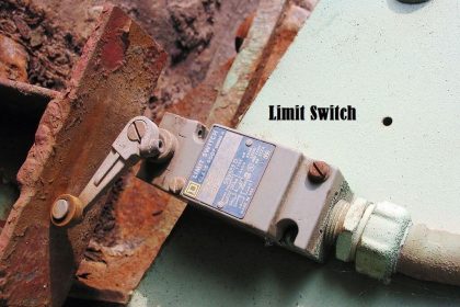
Switches are simplest of all input devices. The Digital Input Card monitors the two states of the switch by measuring the voltage on the sense circuit.

There are two types of voltage sensing circuits used with switches;

  1. The pull-down circuit
  2. The pull-up circuit.

Basically, the pull-down circuit will close the switch to ground and the pull-up circuit will close the switch to voltage.

Pull-down switch circuit

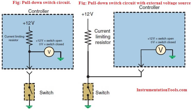
A pull-down voltage sense circuit usually uses an internal voltage source within the processor card. It is also possible to use an external voltage source. The current limiting resistor is used to protect the processor card and the circuit. It also prevents input values from floating. Floating occurs when the switch is open resulting in the input to the voltage sense circuit of the control module being susceptible to electrical noise that may cause the control module to misread the switch state. The current limiting resistor used in the circuit is referred to as a pull-up resistor since it assures the proper high voltage reading by connecting the voltage sense circuit to an electrical potential that can be removed when the switch is closed.

Pull-up switch circuit.

The pull-up resistor is usually of a very high ohms value to keep amperage to a minimum.

This resistor can have a value of 10K to 10M ohms. When the switch is open, there is no current flow through the resistor and no voltage drop over it. This results in the voltage sense circuit recording a value equal to the reference voltage. When the switch is closed, current flows through the resistor and results in a voltage drop. Since the switch should provide a clean contact to ground, the voltage sense circuit should read a value close to 0 volts.

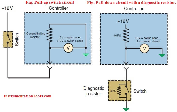
The pull-up circuit will have a reference voltage through the switch. Usually the reference voltage will be provided directly from the battery or by the ignition switch. The current limiting resistor performs the same function in this circuit as it does in the pull-down circuit. This resistor is referred to as a pull-down resistor since it assures a proper low voltage reading by preventing float when the switch is open. With the switch in the open position the voltage sense circuit will read 0 volts. With the switch closed, the sense circuit should read close to reference voltage.

Both of these circuits are limited concerning the ability to determine circuit faults. Since there are only two states for the switch, there are two voltage values that the processor card expects to see. An open or short to ground will not produce an unexpected voltage value, but will result in improper system operation. However, the processor card may be capable of determining an functionality problem with the input circuit if the seen voltage is implausible for the conditions. For example, if the switch is an operator activated switch that requests A/C operation and the voltage indicates that the switch may be stuck the processor card can set a stuck switch DTC and ignore the input.

To provide continuity diagnostics, the circuit may have a diagnostic resistor wired parallel to the switch. The processor card will be able to recognize three different voltage values. In the example, the current limiting resistor has a value of 10K ohms while the diagnostic resistor has a value of 2K ohms. With the switch in the open state, the voltage sense circuit would read 10 volts. With the switch closed the voltage read will be close to 0 volts. A reading of 12 volts would indicate an open in the circuit.Resistive mutiplex switch

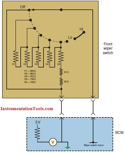
Another typical type of switch that is used is the resistive multiplex switch. This switch is used to provide multiple inputs from a single switch using one circuit. The control module sends a signal voltage to the switch through a fixed resistor. Each switch position has an unique resistance value that will be placed in series with the resistor in the control module. As different switch positions are selected, a different amount of voltage is dropped over the fix resistor in the control module and the sensed voltage level changes. Based on the sensed voltage value, the control module interprets what operation the driver is requesting.

Also Read: Basics of Switches

Don't Miss Our Updates
Be the first to get exclusive content straight to your email.
We promise not to spam you. You can unsubscribe at any time.
Invalid email address
You've successfully subscribed !
Cable Screen shall not be Grounded at Field Device ?
Design Logic Diagrams with Standard Formats for Process Control
Float Level Switch Working Principle
How to Select a Fuse ?
Process Control Systems Philosophy Concept
Share This Article
Facebook Whatsapp Whatsapp LinkedIn Copy Link
Share
Leave a Comment

Leave a Reply Cancel reply

Your email address will not be published. Required fields are marked *

Stay Connected

128.3kFollowersLike
69.1kFollowersFollow
208kSubscribersSubscribe
38kFollowersFollow

Categories

Recent Comments

  • Guifty Shimica on Top Non-PLC Certification Courses for Automation Professionals
  • Guifty Shimica on Top Non-PLC Certification Courses for Automation Professionals
  • MIHARITSOA Aina Sitraka on Top Non-PLC Certification Courses for Automation Professionals
  • Vaishnavi on Free Instrumentation Course for Trainee Engineers

Related Articles

History of 3-15 psi, 10-50 mA, and 4-20 mA signals

History of 3-15 psi, 10-50 mA, and 4-20 mA signals

Instrument Control Package (ICP)

Package Control and Safety Systems Implementation Methods

Selection Criteria of PH Analyzer

Selection Criteria of pH Analyzers

Monsoon Protection for Field Instruments and Junction Boxes

Monsoon Protection for Field Instruments and Junction Boxes

Heat Tracing Problems

Heat Tracing Problems

What is the thermal effect on zero

What is the thermal effect on Sensors?

Vortex Flow Meters

All About Vortex Flow Meters

Instrument Air (IA) System

Process Design of Instrument Air System

More Articles

Level Control Valve with Horizontal Float

Level Control Valve with Horizontal Float

How Nuclear Radiation is used to Measure Coke Dust Level?

How Nuclear Radiation is used to Measure Coke Dust Level?

Stepper Motors Objective Questions & Answers

Stepper Motors Objective Questions & Answers

Capacitive Tank Gauges

Capacitive Tank Gauges

Liapunov’s Stability Analysis

Direct Method & Constructing of Liapunov for the Linear & Non-Linear System

What is a Multi-Core Cable

Difference Between Single Core and Multi-Core Cables

Displacer interface level measurement Calibration

Displacer Interface Level Measurement

Types of PLC Memory

Types of PLC Memory

Follow US
All rights reserved. Reproduction in whole or in part without written permission is prohibited.
Welcome Back!

Sign in to your account

Username or Email Address
Password

Lost your password?