Proximity sensors are often used in machine vibration monitoring to measure the variation in distance between a shaft and its support bearing. Basically it is relative vibration measurement.
This is common in large critical machines like steam turbines, compressors, and motors that use sleeve-type bearings. The voltage is sent from the power supply through the oscillator demodulator to the probe tip. The distance from the probe tip to the shaft determines how much of this supplied voltage is returned back to the monitor through the extension cable and oscillator demodulator. It is usually a 3 wire circuit.
There is only one distance associated with any given voltage.
The aim of this article is to showcase the use of the proximity sensors beyond the relative vibration measurement, which is to determine the lifting of the shaft.
A jacking oil (and pump) is used on rotor shafts of the Turbine/compressor to provide even cooling of the shaft and eliminate rotor distortion caused by sags due to weight and bows due to uneven cooling. It is essential to measure whether a shaft is evenly jacked up by oil prior to the start-up of critical rotary equipment like a turbine/compressor.
This can be achieved during the initial alignment of the rotor by the OEM engineer with the help of a micrometer pointer placed on the shaft. Once it is jacked up, the needle on the shaft will move and show the reading.
This article elaborates on another method to determine shaft jacked up or not and how much jacked up so that it helps OEM engineers to troubleshoot any disturbance in a critical machine. Sometimes it also helps to determine the oil flow through variable orifice installed in oil lines used for jacking purposes.
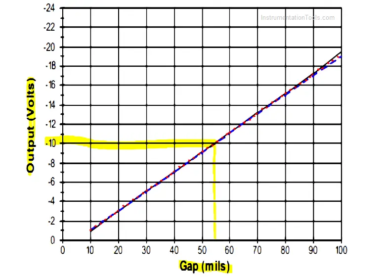
Say, for example, a machine is installed with Bentley Nevada proximity transducer system [3300 XL 8 mm], as per the catalog of this proximity sensor, the sensitivity of the probe is 7.87 V/mm or 200 mV/mil (it is understood that proximity probe is installed within the distance specified in the catalog).
The below graph is available in the catalog, which shows the sensor linear range. Suppose proximity probes are set at -10V output, it means that the gap between sensor and shaft is ~55 mils. This is reading prior to jacking.

The actual installation of proximity probes will be as per the below figure. i.e. sensor (proximity probes) are placed at a 45-degree angle with respect to the horizontal and vertical centerline.
When the Jacking oil pump is started, and the shaft is lifted at that time, naturally, the gap between the probe and shaft will reduce. This is what we want to measure! Suppose after jacking, proximity reading went to -8 VDC.
So 2VDC is reduced, which means that (7.87 VDC-> 1 mm then 2VDC->mm?) 0.25 mm (~10 mils) Gap has been reduced between probe and shaft with respect to earlier. This is the way that proximity probe can be used as distance measurement as the shaft is not rotating, it is only lifted.
For illustration purposes, proximity reading before and after is attached to get better clarity. These reading also serves the records for future maintenance.
Now take the case 1 from the above proximity probe readings,
Using Pythagoras formula, (2Z)2 = X2 + Y2… when we have X=Y then Z = [1 / √2 ] * X
X and Y can be known from Gap vs Voltage output.
For above example, Z = [1 / √2 ] * 10 = 7.07 mils (0.18 mm) has been jacked up due to jacking oil.
This can be rechecked with your field pointer dial reading. Once the proximity reading matches the field reading, this will reduce the time for the OEM engineer when he finds improper jacking.
Although proximity sensors are used for various diagnostic analysis, for rotary equipment this proximity sensor reading helps calculating the actual jacking during initial installation and related maintenance & troubleshooting as this reading will serve as a base condition of shaft/rotor with respect to the casing.
Author: Jatin Katrodiya
This article is about controlling the Pneumatic cylinder and Pneumatic motor in the assembly line…
In this post, we will learn the basic requirements for a network switch to be…
The PLC panel and MCC panel interface signals are start, stop, run feedback, trip, local…
In this article, we are going to discuss about shutter door control using induction motor…
Electrical Drives control the motion of electric motors. Motion control is required in industrial and…
PLC ladder logic design to control 3 motors with toggle switch and explain the program…
View Comments
Hi,
Can you explain how you measured shaft lifting w.r.t center?