Proper sizing of conductors is determined by many factors such as industry standards, insurance requirements, local codes, etc.
The following is based on many years of experience and NFPA 77 “Static Electricity,” 1994. There is no single answer to conductor sizing, although the following guidelines can be provided:
1. Conductors which are connected and disconnected frequently should be light enough to provide an adequate life. A 1/8 inch stainless steel, No. 6 AWG extra flexible copper, 3/16 inch flexible bronze or galvanized steel will carry the current required for static grounding and will fit the majority of applications.
2. Permanently mounted conductors are generally recommended to be at least No. 6 AWG copper, although conductors of #2 to 2/0 are generally used because they are more sturdy. Copper busbar is often used where mounted on a wall or floor. The minimum size recommended is 1/8 inch by 1 inch
3. Outdoor grounding conductors are generally sized for the particular facility and are larger than the minimum required for static grounding requirements alone. A minimum size of #2 AWG is recommended. If fault currents must be considered, a larger size may be necessary.
The question of insulation is important if the static conductor or clamp comes in contact with an object that may be electrically energized.
Another consideration is the operator being in parallel with the static discharge path. If neither of these is a concern, then most users would probably prefer bare conductors that are easier to inspect.
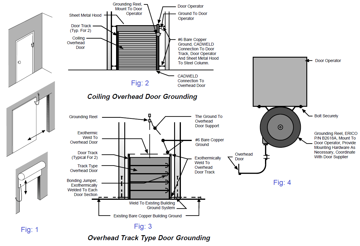
Metal doors must be bonded to the grounding system in critical areas. (Fig. 1, 2, 3, and 4)

A personnel static ground bar is necessary to dissipate any static charge before entering a room. (Fig. 5)
Ground bars are available for attachment of static ground clamps. (Fig. 6)
Various bonding jumpers are available from plain or coiled conductors to reels. (Fig. 7)
Fig: 7
Copper ground busbars should be located at room periphery for easy access for ground clamps. (Fig. 8)
Fig: 8
Reference: erico
Learn an example PLC program to control a pump based on level sensors using ladder…
In the PLC timer application for security camera recording, when motion is detected then camera…
In this example, we will learn batch mixing with PLC ladder logic program using timer…
This PLC example on manufacturing line assembly is an intermediate-level PLC program prepared for the…
In this article, you will learn the PLC programming example with pushbutton and motor control…
This article teaches how to convert Boolean logic to PLC programming ladder logic with the…