Inst ToolsInst ToolsInst Tools
  • Courses
  • Automation
    • PLC
    • Control System
    • Safety System
    • Communication
    • Fire & Gas System
  • Instrumentation
    • Design
    • Pressure
    • Temperature
    • Flow
    • Level
    • Vibration
    • Analyzer
    • Control Valve
    • Switch
    • Calibration
    • Erection & Commissioning
  • Interview
    • Instrumentation
    • Electrical
    • Electronics
    • Practical
  • Q&A
    • Instrumentation
    • Control System
    • Electrical
    • Electronics
    • Analog Electronics
    • Digital Electronics
    • Power Electronics
    • Microprocessor
  • Request
Search
  • Books
  • Software
  • Projects
  • Process
  • Tools
  • Basics
  • Formula
  • Power Plant
  • Root Cause Analysis
  • Electrical Basics
  • Animation
  • Standards
  • 4-20 mA Course
  • Siemens PLC Course
Reading: Define Normal Status for each of the Process Switch
Share
Font ResizerAa
Inst ToolsInst Tools
Font ResizerAa
  • Courses
  • Design
  • PLC
  • Interview
  • Control System
Search
  • Courses
  • Automation
    • PLC
    • Control System
    • Safety System
    • Communication
    • Fire & Gas System
  • Instrumentation
    • Design
    • Pressure
    • Temperature
    • Flow
    • Level
    • Vibration
    • Analyzer
    • Control Valve
    • Switch
    • Calibration
    • Erection & Commissioning
  • Interview
    • Instrumentation
    • Electrical
    • Electronics
    • Practical
  • Q&A
    • Instrumentation
    • Control System
    • Electrical
    • Electronics
    • Analog Electronics
    • Digital Electronics
    • Power Electronics
    • Microprocessor
  • Request
Follow US
All rights reserved. Reproduction in whole or in part without written permission is prohibited.
Inst Tools > Blog > Switches > Define Normal Status for each of the Process Switch

Define Normal Status for each of the Process Switch

Examine process switches normal status, such as pressure switch, level switch, temperature switch, and flow switch.

Last updated: September 27, 2020 11:20 am
Editorial Staff
Switches Practical Questions
No Comments
Share
2 Min Read
SHARE

Switches, whether they be hand-actuated or actuated by a physical process, come in two varieties: normally-open (NO) and normally-closed (NC).

You are probably accustomed to seeing both types of switch represented in the pushbutton form on schematic diagrams:

Normally-open pushbutton switches

Normally-open pushbutton switches close (pass current) when actuated (pressed). When un-actuated, they return to their “normal” (open) state.

Normally-closed pushbutton switches are just the opposite: they open (stop current) when actuated (pressed) and return to their “normal” (closed, passing current) state when un-actuated.

This is simple enough to comprehend: the “normal” status of a momentary-contact pushbutton switch is the state it is in when no one is touching it. When pressed, the pushbutton switch goes to the other (opposite) state.

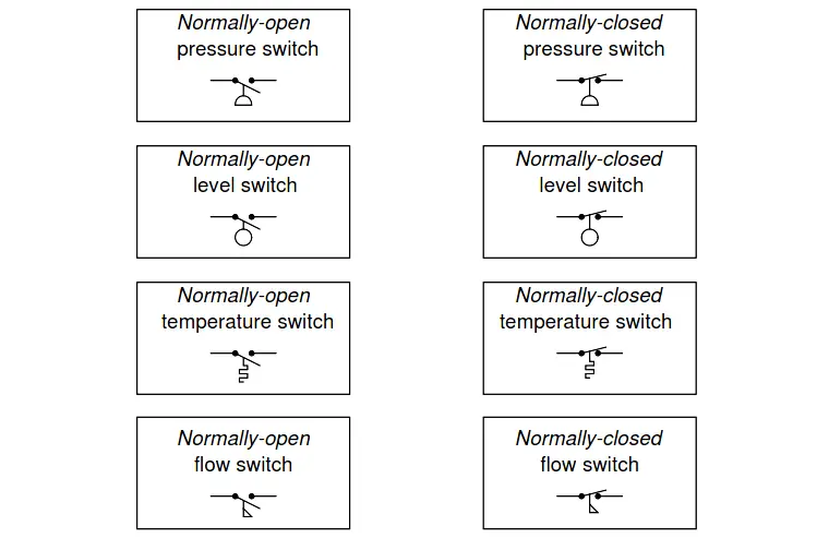
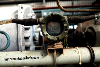
Things get more confusing, though, when we examine process switches, such as pressure switches, level switches, temperature switches, and flow switches:

Process Switch

Process Switches Normal Status

Define “normal” for each of these process switches. In other words, explain what condition(s) each process switch must be in to ensure it is in the “normal” state; and conversely, what condition(s) need to be applied to each switch to force it into its other state.

Answer:

The “normal” condition for a process switch is the condition of the least stimulus.

For example:

  • A pressure switch will be in its “normal” state when there is minimum pressure applied.
  • A level switch will be in its “normal” state when there is no level detected by the switch.
  • A temperature switch will be in its “normal” state when it is cold.
  • A flow switch will be in its “normal” state when there is no flow detected by the switch.

Read Next:

  • Design of Switch Contact
  • Make/Break Sequence
  • Diode Switching Circuits
  • PLC Switch Example
  • Transistor Switch Principle

Credits: Tony R. Kuphaldt

Don't Miss Our Updates
Be the first to get exclusive content straight to your email.
We promise not to spam you. You can unsubscribe at any time.
Invalid email address
You've successfully subscribed !

Continue Reading

How Much Pressure Indicated by Micromanometer?
Instrument Salesperson Question
What Effect on Hydrostatic Level Transmitter if Liquid Density Changes?
What Affect the Pressure Measurement Accuracy of a Manometer?
Practical Process Control System Questions & Answers – 1
Paddle Wheel Level Switch Principle
Share This Article
Facebook Whatsapp Whatsapp LinkedIn Copy Link
Share
Leave a Comment

Leave a Reply Cancel reply

Your email address will not be published. Required fields are marked *

Stay Connected

128.3kFollowersLike
69.1kFollowersFollow
210kSubscribersSubscribe
38kFollowersFollow

Categories

Explore More

Calculate the Temperature of 4 Wire RTD
Programmable Logic Controller (PLC) Questions and Answers – 6
Programmable Logic Controller (PLC) Questions and Answers – 7
Calculate Hydraulic Pressure of a Process Vessel
Vibration Switch Working Principle
Microwave Barrier Level Switch Working Principle
Air Compressor Control Circuit Problem
Questions on Dip Tube Type Level System

Keep Learning

Thermocouple measurement and reference junction temperatures

Thermocouple Measurement and Reference Junction Temperatures

Galileo thermometer Principle

Galileo Thermometer

PSV lift pressure

Calculate PSV Lift Pressure

10 Questions on Reforming Furnace Control System

10 Questions on Reforming Furnace Control System

Inductive proximity switches

How to Connect Proximity Switch (Source Type) to Make LED ON ?

level control system

Practical Process Control System Questions & Answers – 10

Calculate the Thermocouple’s Measurement Junction Temperature

Calculate the Thermocouple’s Measurement Junction Temperature

Determine the Pressure at Each Port of DP Transmitter

Determine the Pressure at Each Port of DP Transmitter

Learn More

Communication Protocols in PLC

Various Communication Protocols in PLC

Chemical Battery

Batteries

FPGA vs. CPLD - What are the differences between them

FPGA vs. CPLD – What are the differences between them

Gas Valve Sizing

Gas Valve Sizing

Digital Electronics Objective Questions

Digital Electronics Objective Questions – Set 6

Building Management System

Building Management System

Time Response Analysis

Standard Test Signals Objective Questions

Electrical Machines Questions and Answers

Starting of Polyphase Induction Motors Quiz

Menu

  • About
  • Privacy Policy
  • Copyright

Quick Links

  • Learn PLC
  • Helping Hand
  • Part Time Job

YouTube Subscribe

Follow US
All rights reserved. Reproduction in whole or in part without written permission is prohibited.
Welcome Back!

Sign in to your account

Username or Email Address
Password

Lost your password?