Inst ToolsInst ToolsInst Tools
  • Courses
  • Automation
    • PLC
    • Control System
    • Safety System
    • Communication
    • Fire & Gas System
  • Instrumentation
    • Design
    • Pressure
    • Temperature
    • Flow
    • Level
    • Vibration
    • Analyzer
    • Control Valve
    • Switch
    • Calibration
    • Erection & Commissioning
  • Interview
    • Instrumentation
    • Electrical
    • Electronics
    • Practical
  • Q&A
    • Instrumentation
    • Control System
    • Electrical
    • Electronics
    • Analog Electronics
    • Digital Electronics
    • Power Electronics
    • Microprocessor
  • Request
Search
  • Books
  • Software
  • Projects
  • Process
  • Tools
  • Basics
  • Formula
  • Power Plant
  • Root Cause Analysis
  • Electrical Basics
  • Animation
  • Standards
  • 4-20 mA Course
  • Siemens PLC Course
Reading: The Principle of Dead Weight Pressure Tester
Share
Font ResizerAa
Inst ToolsInst Tools
Font ResizerAa
  • Courses
  • Design
  • PLC
  • Interview
  • Control System
Search
  • Courses
  • Automation
    • PLC
    • Control System
    • Safety System
    • Communication
    • Fire & Gas System
  • Instrumentation
    • Design
    • Pressure
    • Temperature
    • Flow
    • Level
    • Vibration
    • Analyzer
    • Control Valve
    • Switch
    • Calibration
    • Erection & Commissioning
  • Interview
    • Instrumentation
    • Electrical
    • Electronics
    • Practical
  • Q&A
    • Instrumentation
    • Control System
    • Electrical
    • Electronics
    • Analog Electronics
    • Digital Electronics
    • Power Electronics
    • Microprocessor
  • Request
Follow US
All rights reserved. Reproduction in whole or in part without written permission is prohibited.
Inst Tools > Blog > Calibration > The Principle of Dead Weight Pressure Tester

The Principle of Dead Weight Pressure Tester

In this post, we learn the principle of the dead weight pressure tester and the types of pressure gauge calibration methods.

Last updated: September 28, 2022 3:24 pm
Saurabh Vaidya
Calibration Pressure Measurement
No Comments
Share
5 Min Read
SHARE

In this post, we learn the principle of the Dead Weight Pressure Tester.

Contents
Types of Pressure Gauges CalibrationPrinciple of Dead Weight Pressure Tester

(Also called as Dead weight piston gauge or Pressure balance)

Types of Pressure Gauges Calibration

Pressure gauges can be calibrated with one of the following methods:

  1. Using Dead weight tester by calculating the actual pressure generated with the help of area of the piston, local ‘g’ and applied known mass.
  2. Using Dead weight tester by comparison method using the nominal pressure values mentioned on the pressure weights of the Dead weight tester.
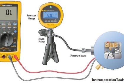
  3. Using Digital Pressure Calibrator.
  4. By comparison method using a Digital pressure gauge and pressure generating system

The comparison between the measurement values of the instrument to be calibrated and the reference standard can be performed by two different methods:

 1) Adjustment of the pressure according to the indication of the instrument to be calibrated, Reading as per set on UUC

2) Adjustment of the pressure according to the indication of the reference standard. Reading as per set on Reference Standard

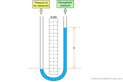
Primary or Fundamental Method for Calibration of Pressure Gauge is a realization from the formula

P= F/A   I.e. Pressure = Force/ Area.

SI unit for pressure is Pascal. I.e. Newton/Metre2

Principle of Dead Weight Pressure Tester

Dead weight Tester consists of an accurately machined piston of known weight which is inserted into a closed fitting cylinder of known cross-sectional area.

Weights of known mass are loaded on one end of the piston and the fluid (Air/Oil/Water) pressure is applied to the other end of the piston until enough force is developed to lift the piston.

Principle of Dead Weight Pressure Tester

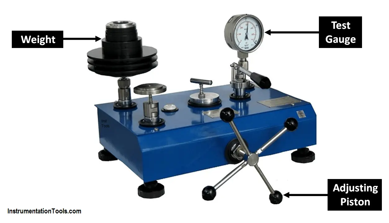
When the piston is floating freely within the cylinder (between limit stops), the piston is in equilibrium with the unknown system pressure. So the applied pressure is equal to the ratio of force due to the weight-piston and the area of cross-section of the piston cylinder.

A pressure balance is an instrument intended for measuring the pressure, based upon the principle of balancing the force produced by the measured pressure on a known area of known loaded weights, as realized with a piston-cylinder assembly.

A pressure balance consists of a vertical piston freely rotating within a cylinder. The two elements of well-machined quality define a surface called the ‘effective area‘.

The pressure to be measured is applied to the base of the piston, creating an upward vertical force.

This force is equilibrated by the gravitational downward force due to masses submitted to the local gravity and placed on the top of the piston. The piston is a part of the load.

The general definition of the pressure measured by the balance is obtained by analyzing the different components of the forces applied to the system.

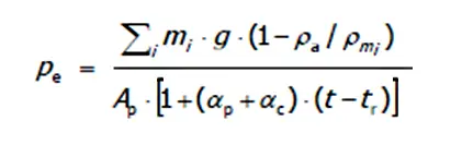
For the Gas-operated Pressure Balance in gauge mode, the pressure definition is as follows:

Pressure= Force/ Area ;

Where Force = Mass X Acceleration due to gravity

F=m.g

Dead weight Tester Formula

Where:

∑ is Summation

Pe is the gauge pressure measured at the bottom of the piston,

mi is the individual mass value of each weight applied on the piston, including all floating elements,

g is the local gravity,

ρa is the density of air,

ρmi is the density of each weight,

Ap is the effective area of the piston-cylinder assembly at a reference temperature t

αp is the linear thermal expansion coefficient of the piston,

αc is the linear thermal expansion coefficient of the cylinder,

t is the measured temperature of the piston-cylinder assembly during its use,

tr is the reference temperature of the piston-cylinder assembly (usually 20 °C).

For the Liquid-operated Pressure Balance, a similar expression could be considered, and the force due to the surface tension of the liquid has to be added to the gravitational force:
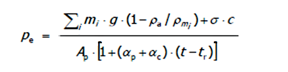
Dead weight piston gauge pressure Formula

Where:

σ is the surface tension of the liquid,

c is the circumference of the piston or its extension at the level where it emerges from the oil.

If you liked this article, then please subscribe to our YouTube Channel for Instrumentation, Electrical, PLC, and SCADA video tutorials.

You can also follow us on Facebook and Twitter to receive daily updates.

Read Next:

  • Types of Calibration
  • Magnehelic Gauge Calibration
  • Selection of Master Instrument
  • Why Calibration is Important?
  • Calibration of Temperature Chamber
Don't Miss Our Updates
Be the first to get exclusive content straight to your email.
We promise not to spam you. You can unsubscribe at any time.
Invalid email address
You've successfully subscribed !

Continue Reading

Pressure Safety Valve Leak Test Procedure (PSV Testing)
Pressure Gauge Water Traps and Pigtail Siphons
Prover Tank Calibration and Mass Flow Meter Verification Procedure
Ammonia Gas Detector Working Principle and Calibration
Smart Transmitter Calibration Tutorial Part 3
Self Actuated Pressure Control Valve Functional Testing
Share This Article
Facebook Whatsapp Whatsapp LinkedIn Copy Link
Share
Leave a Comment

Leave a Reply Cancel reply

Your email address will not be published. Required fields are marked *

Stay Connected

128.3kFollowersLike
69.1kFollowersFollow
210kSubscribersSubscribe
38kFollowersFollow

Categories

Explore More

Different Types of Temperature Calibrators
Differential Pressure Transmitter Working Principle
Closed tank DP Level Transmitter with wet leg elevation zero direct mount Calibration
Motor Operated Valve Functional Testing
Thermocouple Calibration
Scaling Sensor Output to Engineering Units
Pressure Gauge Functional Testing
Uncertainty Calculations of Pressure Calibration

Keep Learning

Commissioning Differential Pressure Transmitter in Boiler Steam Drum

Commissioning a Differential Pressure Transmitter in a Pressurized Boiler Steam Drum

transmitter calibration procedure

Transmitter Calibration Procedure

Pressure Gauge Accessories

Pressure Gauge Accessories Questions and Answers

Absolute and Gauge Pressure

Difference Between Absolute and Gauge Pressure

Pressure Sensor Temperature Effects

Temperature Compensation for Pressure Measurement

Inclined-limb Manometer Formula - 2

Inclined-limb Manometer Principle

Strain Gauge Pressure Sensor Principle

Strain Gauge Pressure Sensor Principle

U tube Manometer Working

Basics of Pressure

Learn More

Discrete control system block diagram

Process Control Instrumentation

Types of Scan Time in a PLC

#16 PLC Best Practices – Create Trend for Cycle Time on HMI

Electric Circuits Objective Questions

Electric Circuits Objective Questions – Set 15

Burst Transformers Root Cause Analysis

Root Cause Analysis – Burst Transformers and 11 kV Input Breakers

Quiz Program Logic Using PLC Programming

Quiz Program Logic Using PLC Programming

Control Valve Packing

Control Valve Packing

Transducers MCQ

Transducers MCQ

Electrical Machines Questions and Answers

Ideal Two Winding Transformer

Menu

  • About
  • Privacy Policy
  • Copyright

Quick Links

  • Learn PLC
  • Helping Hand
  • Part Time Job

YouTube Subscribe

Follow US
All rights reserved. Reproduction in whole or in part without written permission is prohibited.
Welcome Back!

Sign in to your account

Username or Email Address
Password

Lost your password?