Inst ToolsInst ToolsInst Tools
  • Courses
  • Automation
    • PLC
    • Control System
    • Safety System
    • Communication
    • Fire & Gas System
  • Instrumentation
    • Design
    • Pressure
    • Temperature
    • Flow
    • Level
    • Vibration
    • Analyzer
    • Control Valve
    • Switch
    • Calibration
    • Erection & Commissioning
  • Interview
    • Instrumentation
    • Electrical
    • Electronics
    • Practical
  • Q&A
    • Instrumentation
    • Control System
    • Electrical
    • Electronics
    • Analog Electronics
    • Digital Electronics
    • Power Electronics
    • Microprocessor
  • Request
Search
  • Books
  • Software
  • Projects
  • Process
  • Tools
  • Basics
  • Formula
  • Power Plant
  • Root Cause Analysis
  • Electrical Basics
  • Animation
  • Standards
  • 4-20 mA Course
  • Siemens PLC Course
Reading: Pressure Detection Circuit
Share
Font ResizerAa
Inst ToolsInst Tools
Font ResizerAa
  • Courses
  • Design
  • PLC
  • Interview
  • Control System
Search
  • Courses
  • Automation
    • PLC
    • Control System
    • Safety System
    • Communication
    • Fire & Gas System
  • Instrumentation
    • Design
    • Pressure
    • Temperature
    • Flow
    • Level
    • Vibration
    • Analyzer
    • Control Valve
    • Switch
    • Calibration
    • Erection & Commissioning
  • Interview
    • Instrumentation
    • Electrical
    • Electronics
    • Practical
  • Q&A
    • Instrumentation
    • Control System
    • Electrical
    • Electronics
    • Analog Electronics
    • Digital Electronics
    • Power Electronics
    • Microprocessor
  • Request
Follow US
All rights reserved. Reproduction in whole or in part without written permission is prohibited.
Inst Tools > Blog > Pressure Measurement > Pressure Detection Circuit

Pressure Detection Circuit

Last updated: May 25, 2018 11:47 am
Editorial Staff
Pressure Measurement
No Comments
Share
1 Min Read
SHARE

The below Figure shows a block diagram of a typical pressure detection circuit.

Pressure Detection Circuit

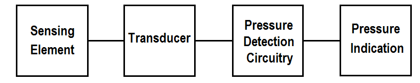
Figure : Typical Pressure Detection Block Diagram

The sensing element senses the pressure of the monitored system and converts the pressure to a mechanical signal. The sensing element supplies the mechanical signal to a transducer, as discussed above.

The transducer converts the mechanical signal to an electrical signal that is proportional to system pressure. If the mechanical signal from the sensing element is used directly, a transducer is not required and therefore not used.

The detector circuitry will amplify and/or transmit this signal to the pressure indicator. The electrical signal generated by the detection circuitry is proportional to system pressure. The exact operation of detector circuitry depends upon the type of transducer used.

The pressure indicator provides remote indication of the system pressure being measured.

Don't Miss Our Updates
Be the first to get exclusive content straight to your email.
We promise not to spam you. You can unsubscribe at any time.
Invalid email address
You've successfully subscribed !

Continue Reading

What is Static Pressure Limit in DP Transmitter ?
Differential Pressure Switch Calibration Procedure
The Principle of Dead Weight Pressure Tester
Differential Pressure Gauge Principle
Differential Pressure Sensors Calibration Procedure
Basics of Pressure switches
Share This Article
Facebook Whatsapp Whatsapp LinkedIn Copy Link
Share
Leave a Comment

Leave a Reply Cancel reply

Your email address will not be published. Required fields are marked *

Stay Connected

128.3kFollowersLike
69.1kFollowersFollow
210kSubscribersSubscribe
38kFollowersFollow

Categories

Explore More

Types of Pressure – Instrument Questions and Answers
Pressure Transmitters Heat-traced impulse lines
Interview Questions on Differential Pressure Flow Transmitter
Pressure Gauges with Bourdon Tube Principle
Impulse Piping standards for Field instruments
Pressure Sensor Specifications
Pressure Transmitter Calibration Procedure
What is Hammer Effect in Gauges ?

Keep Learning

Pressure Transmitter Calibration Setup

Pressure Transmitter Preventive Maintenance

Well Manometer Principle

Well Manometer Principle

C-Bourdon Tube

C-Bourdon Tube Pressure Gauge Theory

Axial Diaphragm Seal Connection

Difference between Axial and Radial Diaphragm Seal Connection?

gauge’s bourdon tube

Pressure Gauges : Remote and Chemical Seals

remote seal capillary type dp transmitter

Closed Tank Remote Seal Capillary type DP Transmitter

DeadWeight Tester

DeadWeight Tester Questions

Pressure Gauge Water traps and pigtail siphons

Pressure Gauge Water Traps and Pigtail Siphons

Learn More

non-contact pyrometers distance calculation

Non-contact Pyrometers Characteristics

Difference between Analog Signal and Digital Signal

What are Analog and Digital Signals? Differences, Examples

Stepper Motor Construction

Stepper Motor Basics, Types, Modes, Wiring, Questions

Token Ring Communication

Token Ring and Token Bus Working Animation

Masking in PLC

What is Masking in PLC?

Electrical bonding jumpers

Proper Sizing of Conductors

Snap Acting Relay Working Principle

Snap Acting Relay Working Principle

PLC Programming Classroom Bell System

Classroom Bell System – PLC Programming Practice Examples

Menu

  • About
  • Privacy Policy
  • Copyright

Quick Links

  • Learn PLC
  • Helping Hand
  • Part Time Job

YouTube Subscribe

Follow US
All rights reserved. Reproduction in whole or in part without written permission is prohibited.
Welcome Back!

Sign in to your account

Username or Email Address
Password

Lost your password?