Inst ToolsInst ToolsInst Tools
  • Courses
  • Automation
    • PLC
    • Control System
    • Safety System
    • Communication
    • Fire & Gas System
  • Instrumentation
    • Design
    • Pressure
    • Temperature
    • Flow
    • Level
    • Vibration
    • Analyzer
    • Control Valve
    • Switch
    • Calibration
    • Erection & Commissioning
  • Interview
    • Instrumentation
    • Electrical
    • Electronics
    • Practical
  • Q&A
    • Instrumentation
    • Control System
    • Electrical
    • Electronics
    • Analog Electronics
    • Digital Electronics
    • Power Electronics
    • Microprocessor
Search
  • Books
  • Software
  • Projects
  • Process
  • Tools
  • Basics
  • Formula
  • Power Plant
  • Root Cause Analysis
  • Electrical Basics
  • Animation
  • Standards
  • 4-20 mA Course
  • Siemens PLC Course
Reading: Compressor Emergency Shutdown Root Cause Analysis
Share
Notification Show More
Font ResizerAa
Inst ToolsInst Tools
Font ResizerAa
  • Courses
  • Design
  • PLC
  • Interview
  • Control System
Search
  • Courses
  • Automation
    • PLC
    • Control System
    • Safety System
    • Communication
    • Fire & Gas System
  • Instrumentation
    • Design
    • Pressure
    • Temperature
    • Flow
    • Level
    • Vibration
    • Analyzer
    • Control Valve
    • Switch
    • Calibration
    • Erection & Commissioning
  • Interview
    • Instrumentation
    • Electrical
    • Electronics
    • Practical
  • Q&A
    • Instrumentation
    • Control System
    • Electrical
    • Electronics
    • Analog Electronics
    • Digital Electronics
    • Power Electronics
    • Microprocessor
Follow US
All rights reserved. Reproduction in whole or in part without written permission is prohibited.
Inst Tools > Blog > Control Systems > Compressor Emergency Shutdown Root Cause Analysis

Compressor Emergency Shutdown Root Cause Analysis

Last updated: June 23, 2020 10:00 pm
Editorial Staff
Control Systems Practical Questions
2 Comments
Share
4 Min Read
SHARE

The compressor emergency shutdown system (ESD) has tripped the natural gas compressor off-line three times in the past 24 hours.

Contents
Compressor Root Cause AnalysisAnswer

Each time the operator goes to reset the compressor interlock, he notices the graphic display panel on the interlock system says “Separator boot high level” as the reason for the trip.

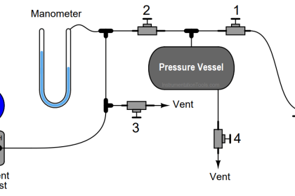
After this last trip, operations decides to keep the compressor shut down for a few hours until your arrival to diagnose the problem. Your first diagnostic test is to look at the indicated boot level in the sight-glass level gauge (LG-93). There, you see a liquid level appears to be normal:

Compressor Root Cause Analysis

compressor emergency shutdown system

Click on the image to Zoom

First, explain why this first diagnostic test was a good idea. Then, identify what would your next diagnostic test be.

Finally, comment on the decision by operations to leave the compressor shut down until your arrival. Do you think this was a good idea or a bad idea, from a diagnostic perspective? Why or why not?

Answer

Given the fact that the ESD system keeps indicating a high boot level, you know that it “thinks” the liquid level inside the boot is higher than it should be.

The next logical step is to determine whether or not a high liquid level condition does indeed exist. If so, the trip is legitimate and there may be a problem with the liquid level control system. If not, the LSHH-231 or its associated wiring may have a fault that sends a false trip alarm to the ESD system.

However, the decision to leave the compressor idle for a few hours until your arrival was not a good one for diagnosis. If indeed there is a problem with excessive liquid collecting in the boot, this would only be evident during running operation.

With the compressor idle and no new gas entering the separator vessel, there will be no new liquid collecting in the boot, which will give the boot level control system ample time to empty that liquid down to a normal level and make it appear as though there is no level problem.

In other words, leaving the compressor idle for a few hours “erases” the evidence, making it more difficult to troubleshoot.

Aside from re-starting the compressor and watching it run, you could perform a test on the liquid level control system by simulating a high-level condition inside the boot (e.g. applying pressure to one side of LT-92) and observing how fast or slow the actual liquid drains out (as indicated by LG-93).

If there is a problem with the level control valve LV-92 or its associated components, you should be able to tell in the form of a long (slow) drain time.

The fact that the blind flange at the bottom of the boot drain line says “Rod out” on the P&ID suggests this line is prone to plugging with debris, which could explain a slow-draining condition and consequently the frequent high-level trips.

Share Your Answers via Comments

Read Next:

  • Interface Level Measurement 
  • Basics of Level Measurement
  • Safety Switches for Conveyors
  • Guided-wave Radar Level 
  • What is Instrumentation Control
Don't Miss Our Updates
Be the first to get exclusive content straight to your email.
We promise not to spam you. You can unsubscribe at any time.
Invalid email address
You've successfully subscribed !

Continue Reading

Questions on Level Switches
Identify Two Pressure Switches Logic
What is DIN rail ?
Building Management System
UPS Selection Factors for a Control System
Practical Process Control System Questions & Answers – 1
Share This Article
Facebook Whatsapp Whatsapp LinkedIn Copy Link
Share
2 Comments
  • Ahmed Hashim says:
    April 2, 2019 at 5:05 pm

    Great topic, RCA,

    Firstly, I agree that leaving the compressor idle for few hours not a good idea for the best diagnostic. However, running the compressor while the liquid level is high that’s not a good idea as well because that would damage the impeller and the other internal parts.

    That’s why they make the safeguarding system to protect the equipment from any abnormal things threatening the safety critical equipment.

    So, the best diagnostic is to be as fast as possible by the field operator to visually check whether the liquid level is high or low by LG and that would not take that much time.

    By the time being, the Field Operator should keep communicating with the CRO to see whether the liquid level is the same as in the field or not and take the correct action by opening the Bypass valve which is supposed to be there to minimize the liquid level in case of the LCV is plugged.

    Reply
  • Jacob Enco says:
    June 17, 2019 at 12:19 pm

    Isn’t this a general diagnostic technique rather than root cause analysis?

    Reply

Leave a Reply Cancel reply

Your email address will not be published. Required fields are marked *

Stay Connected

128.3kFollowersLike
69.1kFollowersFollow
210kSubscribersSubscribe
38kFollowersFollow

Categories

Explore More

Voice Activated Industrial Automation Systems
What is the BACNet Protocol? BACNet IP vs. BACNet MS/TP
Automation System Process Functionalities
How Much Pressure Indicated by Micromanometer?
What is PV Tracking ?
Determining the Design Purpose of Override Controls
Pressure Control Loop Wiring Connections
PLC Program to Control a Water Pump

Keep Learning

Industrial Automation and Control Systems (IACS)

Industrial Automation and Control Systems (IACS)

Loop-powered 4-20 mA transmitter

Loop-powered 4-20 mA Transmitter Circuit Voltage drop

Basics of Loop Checks

Basics of Loop Checks

Two-element drum level control system

Two Element Drum Level Control System

Networked SCADA Architecture

Types of SCADA System Architecture

Which Tube has most Hydrostatic Pressure

Which Tube has most Hydrostatic Pressure?

AI AO DI DO Signals

What are AI, AO, DI, and DO? – Definition, Examples, Purpose

LCS Configuration equipped with LOTO Facility

Motor Control Signal Interface

Learn More

What is Cloud Computing

What is Cloud Computing? Types of Cloud Services, Components

Dahlander Motor Control Circuit

Dahlander Motor Control Circuit and Power Circuit

Nuclear Level Measurement

Nuclear Level Detectors Cascade or Master/Slave concept

hydraulic module

Identify all Spool Valve Positions

Power Electronics Interview Questions & Answers

Power Electronics Interview Questions & Answers

Dry Leg

Calculate 0%, 50%, and 100% Calibration Points for ΔP transmitter

Power Electronics objective questions and answers

30 Important Power Electronics MCQ

Thermal Power Plant

Thermal Power Plant – Basic Layout, Parts, Principle

Menu

  • About
  • Privacy Policy
  • Copyright

Quick Links

  • Learn PLC
  • Helping Hand
  • Part Time Job

YouTube Subscribe

Follow US
All rights reserved. Reproduction in whole or in part without written permission is prohibited.
Welcome Back!

Sign in to your account

Username or Email Address
Password

Lost your password?