In some cases, after isolating a fault to a particular circuit, it may be necessary to isolate the problem to a single component in the circuit.
In this event, you have to apply logical thinking and your knowledge of the symptoms caused by certain component failures.
Some typical component failures and the symptoms they produce are now discussed.
Effect of an Open Diode in a Half-Wave Rectifier
A half-wave filtered rectifier with an open diode is shown in Below Figure. The resulting symptom is zero output voltage as indicated.
This is obvious because the open diode breaks the current path from the transformer secondary winding to the filter and load resistor and there is no load current.
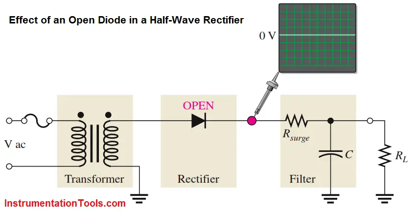
Fig : The effect of an open diode in a half-wave rectifier is an output of 0 V.
Other faults that will cause the same symptom in this circuit are an open transformer winding, an open fuse, or no input voltage.
Effect of an Open Diode in a Full-Wave Rectifier
A full-wave center-tapped filtered rectifier is shown in Below Figure. If either of the two diodes is open, the output voltage will have twice the normal ripple voltage at 50/60 Hz rather than at 100/120 Hz, as indicated.
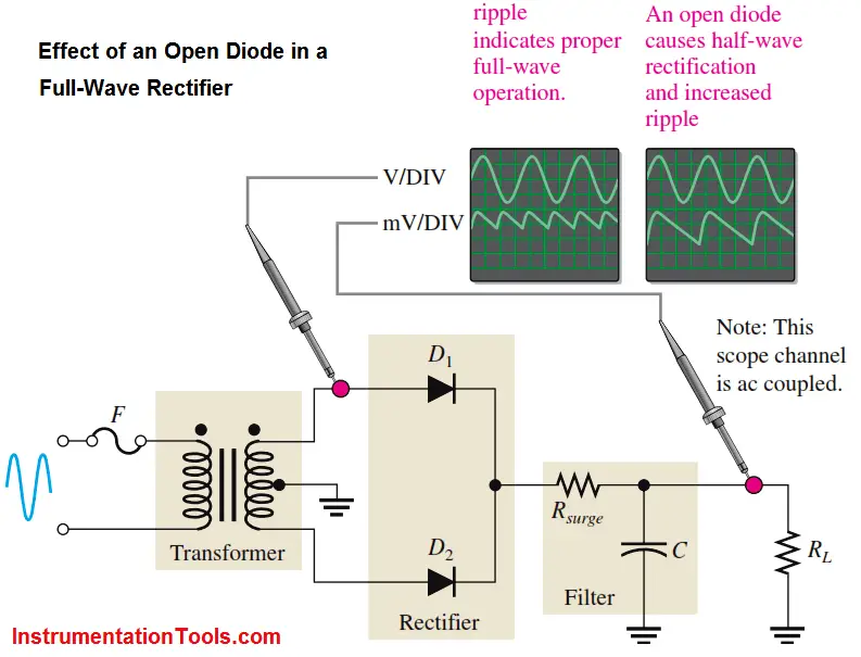
Fig : The effect of an open diode in a center-tapped rectifier is half-wave rectification and twice the ripple voltage at 50HZ / 60HZ.
Another fault that will cause the same symptom is an open in the transformer secondary winding. The reason for the increased ripple at 60 Hz rather than at 120 Hz is as follows.
If one of the diodes in Above Figure is open, there is current through RL only during one half-cycle of the input voltage. During the other half-cycle of the input, the open path caused by the open diode prevents current through RL.
The result is half-wave rectification, as shown in Above Figure, which produces the larger ripple voltage with a frequency of 60 Hz.
An open diode in a full-wave bridge rectifier will produce the same symptom as in the center-tapped circuit, as shown in Below Figure.
The open diode prevents current through RL during half of the input voltage cycle. The result is half-wave rectification, which produces double the ripple voltage at 60 Hz.
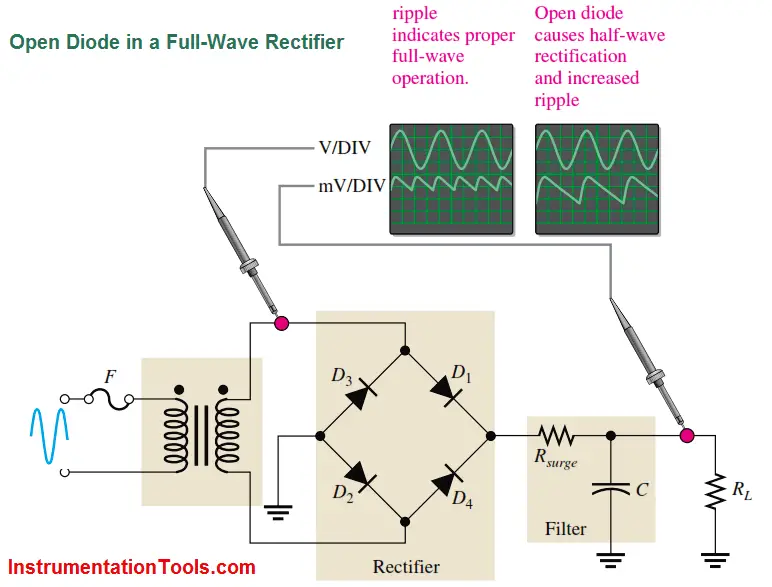
Fig : Effect of an open diode in a bridge rectifier.
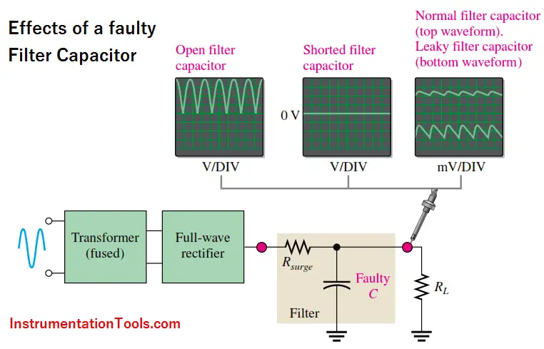
Effects of a Faulty Filter Capacitor
Three types of defects of a filter capacitor are illustrated
- Open : If the filter capacitor for a full-wave rectifier opens, the output is a full-wave rectified voltage.
- Shorted : If the filter capacitor shorts, the output is 0 V. A shorted capacitor should cause the fuse to blow open. If not properly fused, a shorted capacitor may cause some or all of the diodes in the rectifier to burn open due to excessive current. In any event, the output is 0 V.
- Leaky : A leaky filter capacitor is equivalent to a capacitor with a parallel leakage resistance. The effect of the leakage resistance is to reduce the time constant and allow the capacitor to discharge more rapidly than normal. This results in an increase in the ripple voltage on the output. This fault is rare.
Effects of a Faulty Transformer
An open primary or secondary winding of a power supply transformer results in an output of 0 V, as mentioned before.


Good informative
Very educative