Inst ToolsInst ToolsInst Tools
  • Ask
  • Courses
  • Videos
  • Q & A
    • Interview
      • Instrumentation
      • Electronics
      • Electrical
      • Practical Questions
    • MCQ
      • Instrumentation MCQ
      • Electrical MCQ
      • Electronics MCQ
      • Control Systems MCQ
      • Analog Electronics MCQ
      • Digital Electronics MCQ
      • Power Electronics MCQ
      • Microprocessor MCQ
      • Multiple Choice Questions
  • EE
    • Electronics
      • Electronics Q & A
      • Electronic Basics
      • Electronic Devices & Circuits
      • Electronics Animation
      • Digital Electronics
    • Electrical
      • Electrical Basics
      • Electrical Q & A
      • Power Electronics
      • Electrical Machines
      • Electrical Animation
      • Power Systems
      • Switchgear & Protection
      • Transmission & Distribution
  • Measure
    • Control Valves
    • Calibration
    • Temperature
    • Pressure
    • Flow
    • Level
    • Analyzers
    • Switches
    • Vibration
    • Solenoid Valve
  • Control
    • PLC Tutorials
    • Control Systems
    • Safety Instrumented System (SIS)
    • Communication
    • Fire & Gas System
  • More
    • Design
    • Tools
    • Animation
    • Basics
    • Formulas
    • Standards
    • TextBooks
    • Common
    • Software
    • Excel Tools
    • Erection & Commissioning
    • Process Fundamentals
    • Videos
    • Books
Search
All rights reserved. Reproduction in whole or in part without written permission is prohibited.
Reading: Positive & Negative Diode Clippers
Share
Notification Show More
Font ResizerAa
Inst ToolsInst Tools
Font ResizerAa
  • Courses
  • PLC Tutorials
  • Control Systems
Search
  • Ask
  • Courses
  • Videos
  • Q & A
    • Interview
    • MCQ
  • EE
    • Electronics
    • Electrical
  • Measure
    • Control Valves
    • Calibration
    • Temperature
    • Pressure
    • Flow
    • Level
    • Analyzers
    • Switches
    • Vibration
    • Solenoid Valve
  • Control
    • PLC Tutorials
    • Control Systems
    • Safety Instrumented System (SIS)
    • Communication
    • Fire & Gas System
  • More
    • Design
    • Tools
    • Animation
    • Basics
    • Formulas
    • Standards
    • TextBooks
    • Common
    • Software
    • Excel Tools
    • Erection & Commissioning
    • Process Fundamentals
    • Videos
    • Books
Follow US
All rights reserved. Reproduction in whole or in part without written permission is prohibited.
Inst Tools > Blog > Electronic Devices & Circuits > Positive & Negative Diode Clippers

Positive & Negative Diode Clippers

Last updated: October 5, 2016 12:41 pm
Editorial Staff
Electronic Devices & Circuits
No Comments
Share
2 Min Read
SHARE

Diode Biased Limiters/Clippers

First read basics of Diode Clippers. Click Here to read

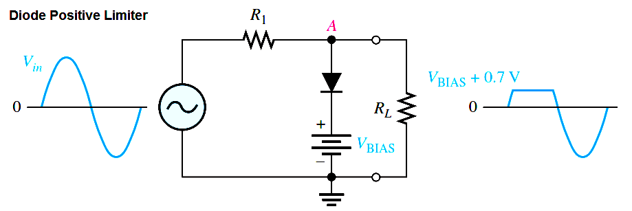
The level to which an ac voltage is limited can be adjusted by adding a bias voltage, VBIAS, in series with the diode, as shown in Below Figure. The voltage at point A must equal VBIAS + 0.7 V before the diode will become forward-biased and conduct. Once the diode begins to conduct, the voltage at point A is limited to VBIAS + 0.7 V so that all input voltage above this level is clipped off.

Diode-positive-limiter

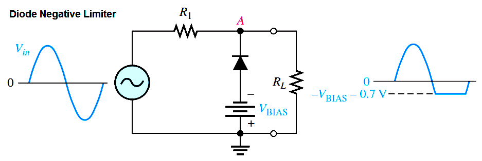
To limit a voltage to a specified negative level, the diode and bias voltage must be connected as in Below Figure. In this case, the voltage at point A must go below -VBIAS – 0.7 V to forward-bias the diode and initiate limiting action as shown.

diode-negative-limiter

By turning the diode around, the positive limiter can be modified to limit the output voltage to the portion of the input voltage waveform above VBIAS – 0.7 V, as shown by the output waveform in Figure (a). Similarly, the negative limiter can be modified to limit the output voltage to the portion of the input voltage waveform below -VBIAS + 0.7 V, as shown by the output waveform in part (b).

diode-clipper

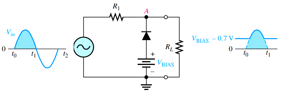
Fig a : Clipper Circuit during Positive Half cycle

diode-clipper-operation

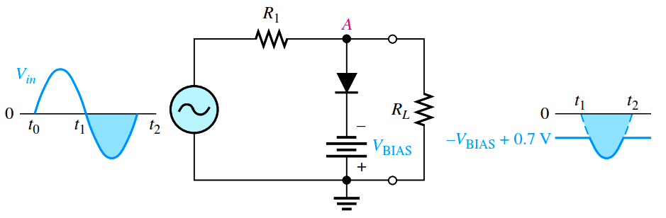
Fig b : Clipper Circuit during Negative Half cycle

Diode Limiter Application

Many circuits have certain restrictions on the input level to avoid damaging the circuit. For example, almost all digital circuits should not have an input level that exceeds the power supply voltage. An input of a few volts more than this could damage the circuit. To prevent the input from exceeding a specific level, you may see a diode limiter across the input signal path in many digital circuits.

Don't Miss Our Updates
Be the first to get exclusive content straight to your email.
We promise not to spam you. You can unsubscribe at any time.
Invalid email address
You've successfully subscribed !
Forward Bias & Reverse Bias of a Diode
Diodes Voltage Quadrupler
Summary Of Transistor Bias Circuits
Basics of Voltage Regulators
CRT Fluorescent Screen
Share This Article
Facebook Whatsapp Whatsapp LinkedIn Copy Link
Share
Leave a Comment

Leave a Reply Cancel reply

Your email address will not be published. Required fields are marked *

Stay Connected

128.3kFollowersLike
69.1kFollowersFollow
208kSubscribersSubscribe
38kFollowersFollow

Categories

Recent Comments

  • Guifty Shimica on Top Non-PLC Certification Courses for Automation Professionals
  • Guifty Shimica on Top Non-PLC Certification Courses for Automation Professionals
  • MIHARITSOA Aina Sitraka on Top Non-PLC Certification Courses for Automation Professionals
  • Vaishnavi on Free Instrumentation Course for Trainee Engineers

Related Articles

Transistor-cut-off-saturation-active-regions

Transistor Cut off, Saturation & Active Regions

Electron Gun of CRT

Electron Gun of Cathode Ray Tube

capacitor-filter-ripples

Ripple Voltage in Rectifiers

Choke Input Filter Operation

Choke Input Filter Operation

photo-diode

Photodiode Working Principle

Semiconductors Diodes Questions & Answers

Semiconductors Diodes Questions & Answers

Optocoupler Principle

Optocouplers Working Principle

Basics of Amplifiers Interview Questions

Amplifiers Questions & Answers

More Articles

Valve Pneumatic Actuator

What is a Pneumatic Actuator ?

Digital Electronics Projects

Top 100 Digital Electronics Project Ideas for Engineering Students

Shielded Cables

The Idea Behind Shielded Cables

Asynchronous Motor Animation

Asynchronous Motor Animation

Programmable Logic Controller (PLC) Questions and Answers

Programmable Logic Controller (PLC) Questions and Answers – 2

Temperature Sensors Questions

Questions on Thermocouple and Pyrometer

7 Marketing Strategies for Engineering Companies

7 Marketing Strategies for Engineering Companies

Control Systems Stability and Algebraic Criteria

Concept of Stability in Control Systems

Follow US
All rights reserved. Reproduction in whole or in part without written permission is prohibited.
Welcome Back!

Sign in to your account

Username or Email Address
Password

Lost your password?