Inst ToolsInst ToolsInst Tools
  • Courses
  • Automation
    • PLC
    • Control System
    • Safety System
    • Communication
    • Fire & Gas System
  • Instrumentation
    • Design
    • Pressure
    • Temperature
    • Flow
    • Level
    • Vibration
    • Analyzer
    • Control Valve
    • Switch
    • Calibration
    • Erection & Commissioning
  • Interview
    • Instrumentation
    • Electrical
    • Electronics
    • Practical
  • Q&A
    • Instrumentation
    • Control System
    • Electrical
    • Electronics
    • Analog Electronics
    • Digital Electronics
    • Power Electronics
    • Microprocessor
  • Request
Search
  • Books
  • Software
  • Projects
  • Process
  • Tools
  • Basics
  • Formula
  • Power Plant
  • Root Cause Analysis
  • Electrical Basics
  • Animation
  • Standards
  • 4-20 mA Course
  • Siemens PLC Course
Reading: PLC Raw Count Calculation for Pressure Transmitter
Share
Font ResizerAa
Inst ToolsInst Tools
Font ResizerAa
  • Courses
  • Design
  • PLC
  • Interview
  • Control System
Search
  • Courses
  • Automation
    • PLC
    • Control System
    • Safety System
    • Communication
    • Fire & Gas System
  • Instrumentation
    • Design
    • Pressure
    • Temperature
    • Flow
    • Level
    • Vibration
    • Analyzer
    • Control Valve
    • Switch
    • Calibration
    • Erection & Commissioning
  • Interview
    • Instrumentation
    • Electrical
    • Electronics
    • Practical
  • Q&A
    • Instrumentation
    • Control System
    • Electrical
    • Electronics
    • Analog Electronics
    • Digital Electronics
    • Power Electronics
    • Microprocessor
  • Request
Follow US
All rights reserved. Reproduction in whole or in part without written permission is prohibited.
Inst Tools > Blog > Formulas > PLC Raw Count Calculation for Pressure Transmitter

PLC Raw Count Calculation for Pressure Transmitter

Last updated: March 4, 2021 4:02 pm
Editorial Staff
Formulas PLC Tutorials Pressure Measurement
7 Comments
Share
3 Min Read
SHARE

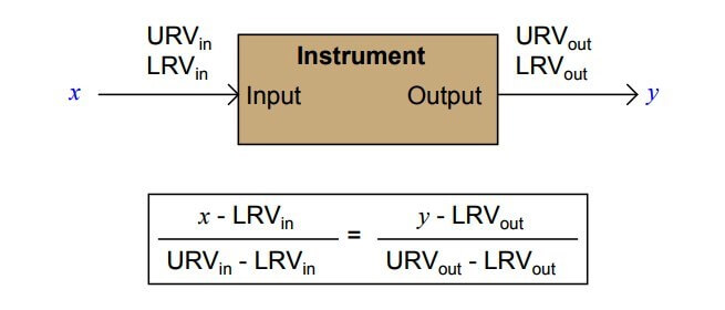
Every instrument has at least one input and at least one output. For instruments responding linearly, the correspondence between input and output is proportional:

PLC Raw Count Calculation

Pressure Transmitter Formula

A practical example of this is a pressure transmitter, in this case one with an input range of 0 to 1023 PSI and an output of 4-20 mA

Pressure Transmitter Calculations

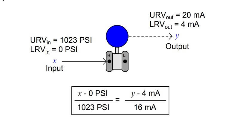
If you happened to measure an output current of 14.7 mA from this pressure transmitter

x = { ( 14.7 – 4 ) / 16 } * 1023 = 684.13 PSI

It would be a simple matter for you to calculate the corresponding input pressure to be 684.13 PSI.

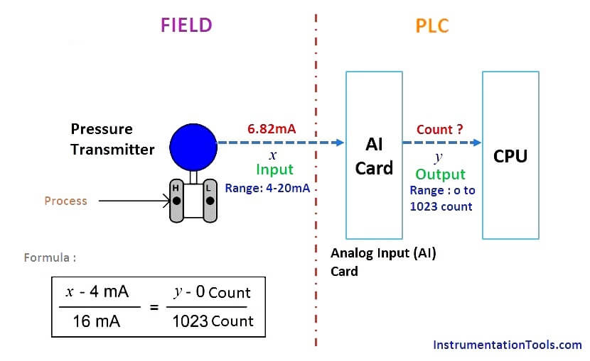
Now consider a pressure transmitter is connected to the PLC system. The pressure transmitter is connected to the Analog input card of the PLC system. The AI card have inbuilt Analog to Digital Converter (ADC). The ADC converts the input 4-20mA value coming from pressure transmitter into equivalent Raw Counts.

The AI card finally sends this Raw counts value to CPU card. The CPU have the pre-defined Pressure transmitter values like its Range (LRV & URV), units etc. The CPU calculates the Process variable (pressure value from pressure transmitter) using these Raw Count from AI card & pre-defined LRV, URV, units etc… and displays the process variable on operator workstations/HMI.

Also Read : Formula to Convert 4-20mA into Process Variable

Take for example this analog-to-digital converter, with a 10-bit output (a “count” range of 0 to 1023) and a 4-20 mA input:

PLC ADC Calculation for Transmitter

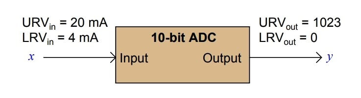
Calculate the corresponding “count” output of this ADC circuit given a 6.82 mA input signal.

Here we are calculating the ADC output in terms of count. So Input to the AI card is “x” and output is “y” as shown in below fig.

PLC Raw Count Calculation formula for Pressure Transmitter

y = { ( 6.82 – 4 ) / 16 } * 1023  = 180 count

In a PLC system, CPU converts this count into equivalent Process variable and displays on the operator workstations.

If you liked this article, then please subscribe to our YouTube Channel for PLC and SCADA video tutorials.

You can also follow us on Facebook and Twitter to receive daily updates.

Read Next:

  • Raw Counts to Engineering Units : Conversion Formula
  • How to Implement Ratio Control in this System?
  • Flowmeter Control Strategy
  • Fieldbus Analog Input Function Block
  • Practical Considerations of ADC Circuits
Don't Miss Our Updates
Be the first to get exclusive content straight to your email.
We promise not to spam you. You can unsubscribe at any time.
Invalid email address
You've successfully subscribed !

Continue Reading

Latching and Unlatching in PLC Programming Example
ControlLogix Architecture – Rockwell Automation
Series Tanks Level Control using PLC Ladder Programming
SAVE and BR Memory Instructions in Siemens PLC Programming
Flood Warning System using Programmable Logic Controller
Conveyor Operation with a Backup Motor using PLC Ladder Diagram
Share This Article
Facebook Whatsapp Whatsapp LinkedIn Copy Link
Share
7 Comments
  • RAGU RAJAN says:
    July 18, 2017 at 2:26 pm

    Dear Mr. S.Bharadwaj Reddy
    I like to say ‘Thank You’ for your wonderful contribution to the people who are in search of knowledge like me for instrumentation and especially about PLC as I m from a Mechanical background; as well inspires me to contribute back to the community.
    Regards
    Rajan.

    Reply
  • Lukkuman hakkim says:
    July 19, 2017 at 5:48 am

    Hello sir,

    very useful article for me ,i got clear idea from this article .thank you very much.

    But one thing, better to check the formula mentioned in the field pressure transmitter to PLC ADC count convertion. in this formula x,y interchangely mentioned.

    Reply
    • S Bharadwaj Reddy says:
      July 19, 2017 at 6:08 am

      Hi Lukkuman hakkim,

      Thank you for the update. Corrected.

      Reply
      • Lukkuman hakkim says:
        July 19, 2017 at 6:16 am

        thank you so much.

        Reply
  • kingsley says:
    August 7, 2017 at 9:30 am

    Thank you sir for your kindness! you are a great man!!

    please how can i scale parameters in logix 500 and logix 5000 controllers

    I need your help on these

    Thanks very much

    Reply
  • Nakkiran says:
    August 17, 2017 at 5:50 am

    Hi Mr.bharadwa reddy first of all thanks for your updation ..

    Can you update what is different between Instrument earthing and electrical earthing ,why it is need separate for earth pits.

    Reply
  • BIKAS GHOSH says:
    September 4, 2019 at 11:42 pm

    Electrical system handles high voltage applications . Instrumentation systems handles low voltages system.

    Instrument earthing is used to ground any noise ( low level interfering signal) in the signals .

    Also instrument earth pit resistance is maintained at low ( nearly 1 ohm )
    .

    If electrical earth is connected with Instruments earth , there is a potential of current flow in between these earthing systems. Hence these two are kept different.

    Reply

Leave a Reply Cancel reply

Your email address will not be published. Required fields are marked *

Stay Connected

128.3kFollowersLike
69.1kFollowersFollow
210kSubscribersSubscribe
38kFollowersFollow

Categories

Explore More

Use of Regions in SCL Language
Pause the Timer PLC Ladder Logic
Ladder Logic Programming Examples
Motor Starter Logic using Siemens PLC Tia Portal
The Purpose of Marshalling Cabinet or Marshalling Panel
SCADA System Vulnerabilities
Formula for Linear mA to Square root mA conversion
WHILE DO Statement in SCL Language

Keep Learning

Percentage-to-Current-Conversion

Formula to Calculate 4-20ma from Percentage

Interposing Relay Panel (IRP)

Interposing Relay Panel (IRP) – Wiring and Testing Requirements

PLC Latched Circuit Example

PLC Latching Function

Structured Text in PLC: Parking Information Systems

Structured Text in PLC: Parking Information Systems

Industrial Automation Projects

Evaluating Industrial Automation Projects Return on investment (ROI)

Pressure Transmitters Filled impulse lines

Pressure Transmitters Filled impulse lines

PLC Count values higher than 999

PLC Count values higher than 999

Electrical Cabinet Air Conditioner

Electrical Cabinet Air Conditioner – Enclosure Cooling, Maintenance

Learn More

PID parameters

PID in Siemens TIA Portal

Process Control Terms

143 Process Control Terms and Glossary – Questions Answers

Emergency ShutDown Valve Working Principle

ESDV : How it Works ?

PLC program for Latching and unlatched circuit

PLC Program for Latching and unlatching Circuit

Brands PLC communication interface and protocol

Communicating Between Siemens PLC and Other PLC Brands

Reliability Techniques for Analyzing Fault Tolerance in Industries

Reliability Techniques for Analyzing Fault Tolerance in Industries

Industrial IoT Job Roles and Responsibilities

IoT Engineer Job Roles and Responsibilities

Centrifugal Compressor outage reduced

Centrifugal Compressor Outage Reduced – Root Cause Analysis

Menu

  • About
  • Privacy Policy
  • Copyright

Quick Links

  • Learn PLC
  • Helping Hand
  • Part Time Job

YouTube Subscribe

Follow US
All rights reserved. Reproduction in whole or in part without written permission is prohibited.
Welcome Back!

Sign in to your account

Username or Email Address
Password

Lost your password?