In this article, you will learn the PLC project examples for EcoStruxure Machine Expert software from the Schneider Electric.
Note: The PLC example is designed for the automation engineers and students to learn the PLC basics.
PLC Project Examples
Problem Statement
Design a PLC ladder logic for the following application.
There is a use of four toggle switches to control four LEDs.
If Switch 1 is ON, then LED I will be ON.
If Switch 2 is ON, then LED II will be ON, and LED I will be OFF.
If Switch 3 is ON, then LED III will be ON, and LED II will be OFF.
If Switch 4 is ON, then LED IV will be ON, and LED III will be OFF.
NOTE: Do not turn the switches OFF once turned ON. (For this Example)
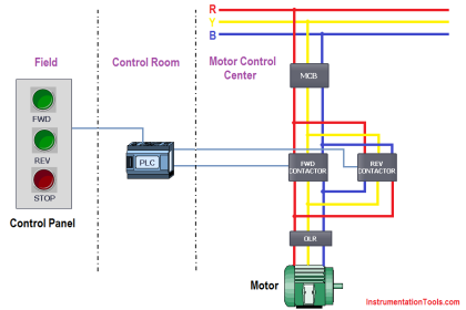
Schneider Electric PLC
In the below video, you can learn this PLC project from start to end with complete details.
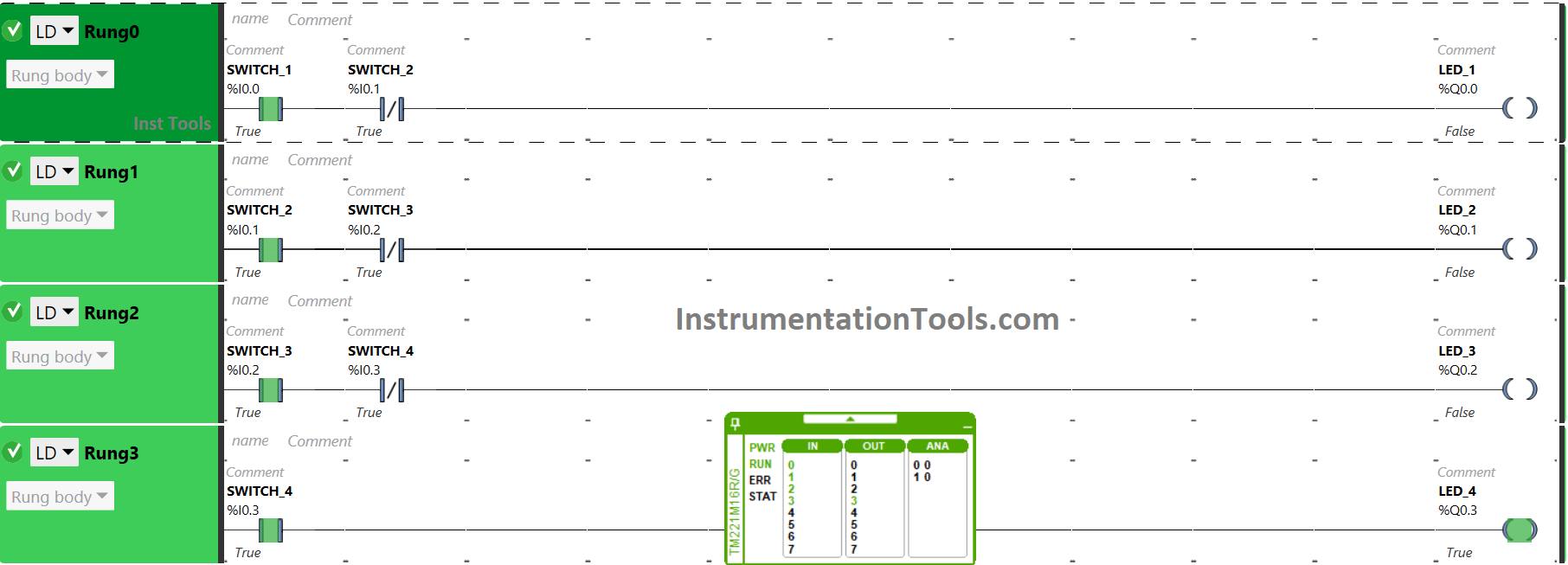
Inputs and Outputs
Digital Inputs:
The required PLC inputs are listed below.
Switch 1: I0.0
Switch 2: I0.1
Switch 3: I0.2
Switch 4: I0.3
Digital Outputs:
The required PLC outputs are listed below.
LED 1: Q0.0
LED 2: Q0.1
LED 3: Q0.2
LED 4: Q0.3
EcoStruxure Machine Expert Ladder Logic
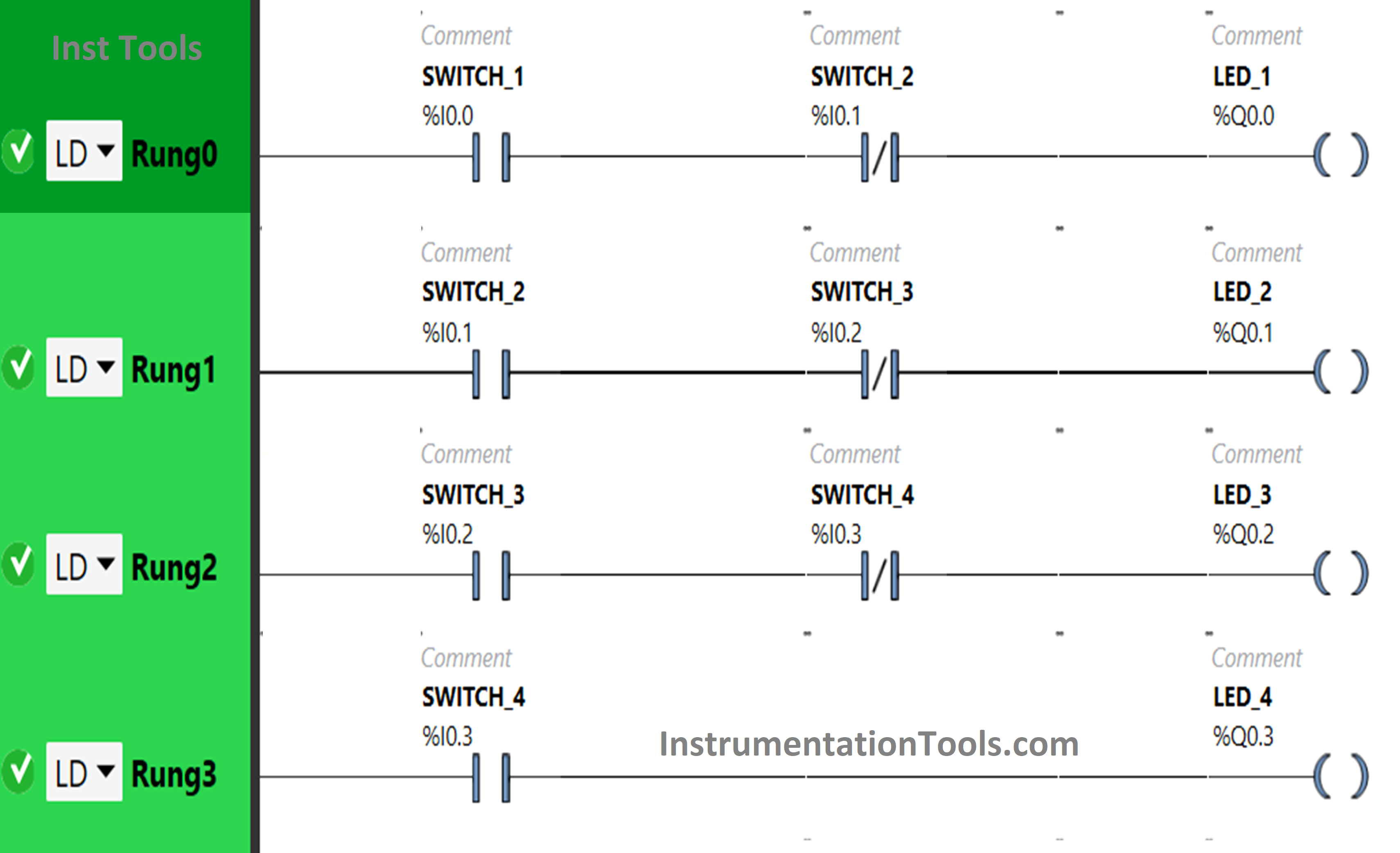
Program Description
For this PLC project, we used EcoStruxure Machine Expert Basic PLC software for programming.
In the above program, we have used Normally Open Contact for Switch 1 (I0.0), Switch 2 (I0.1), Switch 3 (I0.2), and Switch 4 (I0.3).
We have also used Normally Closed Contacts for Switch 2 (I0.1), Switch 3 (I0.2) and Switch 4 (I0.3).
Switch 1 and Switch 4 are connected in series for LED 1, thus implementing AND logic gate. We have also used Normally Closed Contacts for Switch 2, thus implementing the NOT logic gate.
For LED 2, inputs switch 2 and switch 3 are connected in series, thus implementing AND logic gate. We have also used Normally Closed Contacts for Switch 3, thus implementing NOT logic gate.
Switch 3 and switch 4 are implementing OR logic gates i.e., connected in series for LED 3. Switch 4 is taken as Normally Closed Contact, thus implementing NOT logic gate.
Switch 4 only is connected to LED4.
For LED 1 to be ON, Switch 1 should be ON, and Switch 2 should be OFF.
To turn ON LED 2, Switch 2 should be ON, and Switch 3 should be OFF.
When Switch 3 is ON and Switch 4 is OFF, then LED 3 will turn ON.
LED 4 will turn ON when Switch 4 is turned ON.
PLC Programming Simulation
Here we will see the PLC program simulation results with different input combinations.
When Switch 1 is ON
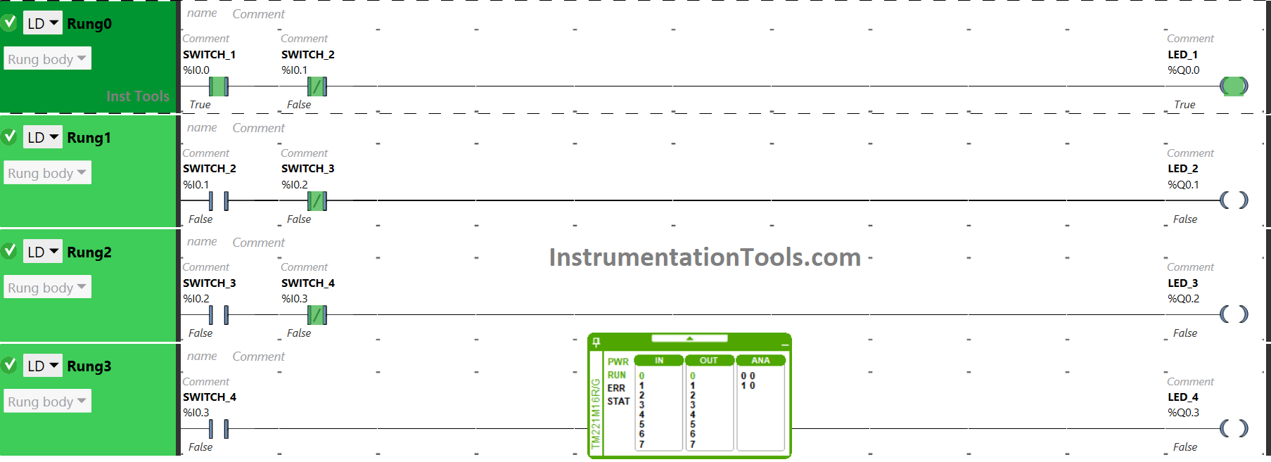
When toggle switch 1 is turned ON and Switch 2 is OFF, the signal flows through it as Switch 2 is used as Normally Closed Contact. As a result, LED 1 gets ON. Other LEDs will remain OFF because Switch 1 is not connected to them.
When Switch 2 is ON
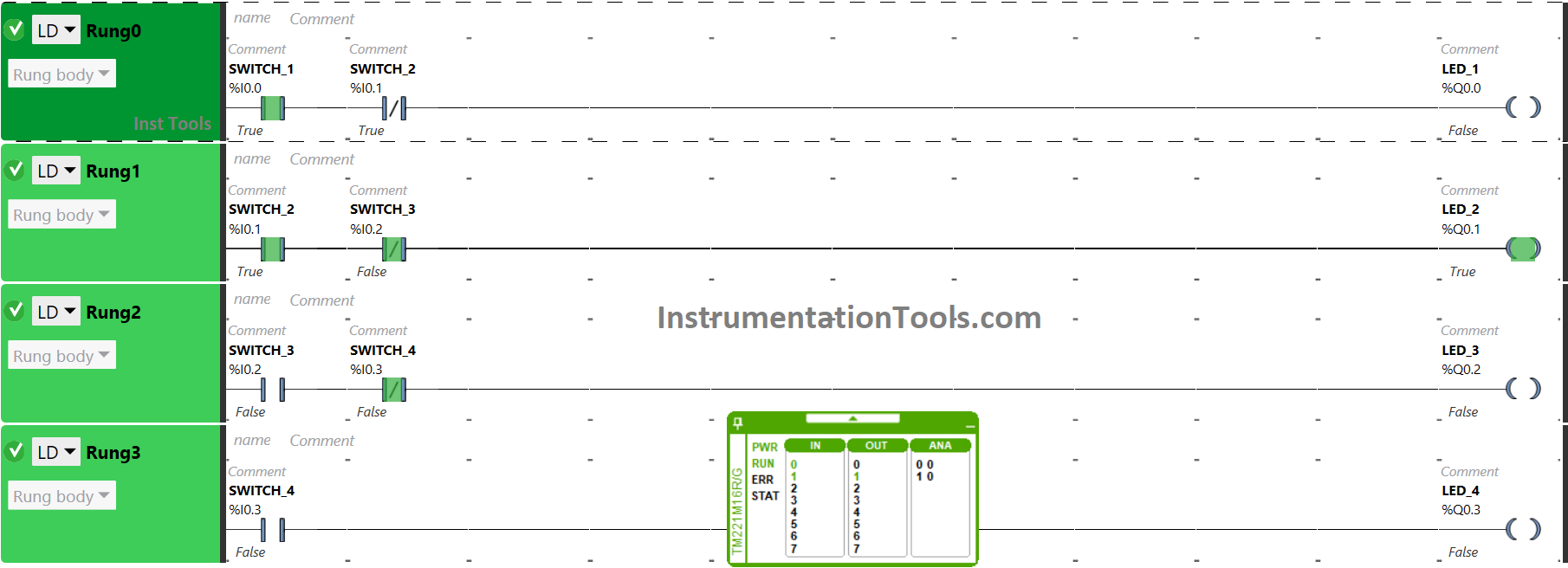
The signal will flow through switch 2 when it is turned ON that will turn ON LED 2. It is so because switch 2 as Normally Open Contact is not connected to other LEDs. Turning ON Switch 2 will also turn OFF LED 1 as it is used as Normally Closed Contact. It will not allow the signal to LED 1.
When Switch 3 is ON
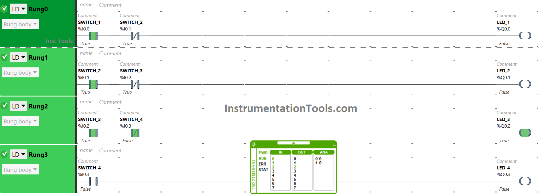
When Switch 3 is turned ON, the signal flows through it that will turn LED 3 ON. The input switch 3 as Normally Open Contact is connected to it only. LED 2 will turn OFF as Switch 3 is used as Normally Closed Contact for LED 2.
When Switch 4 is ON
Switch 4 will turn ON LED 4 when turned ON. Switch 4 as Normally Closed Contact is connected to LED 3. As a result, turning ON Switch 4 will turn OFF LED 3.
If you liked this article, then please subscribe to our YouTube Channel for PLC and SCADA video tutorials.
You can also follow us on Facebook and Twitter to receive daily updates.
Read Next:
- Siemens Control System (TDC)
- How to use PLC with SQL Database?
- Templates in FactoryTalk View Studio
- Control Algorithms in PLC Programming
- Single-acting Cylinder OR Logic Operation


by using schnider ecostruxure machine expert We have four cooling fan 1,2,3,4 If Temperature raises above 270 C → Fan 1 Should run If Temperature rises above 300 C → Fan 1 & 2 Should run If Temperature raises above 350???? → Fan 1,2 & 3 Should run If Temperature raises above 400???? → Fan 1,2,3 & 4 Should run . Write a PLC Program for this application using PLC software draw a plc ladder diagram