I have noticed a very common logic for PLC programmers to develop when they are new – a traffic light sequence. They try it in ladder logic and yes, it works. It is true that newcomers must first try to develop PLC programs in ladder logic, as it is easier to learn. But once they become proficient in it, they must try to use new languages which will reduce their task. One such language is a functional block diagram. In this post, we will see how to develop a PLC program for traffic light sequences using a functional block diagram.
PLC Program for Traffic Light Sequence
Let us understand the case first. We have three lights – red, yellow and green. They turn on after every fixed time interval, in the way that we see on streets. As long as the system is running, these lights will turn on and off in a sequence. The logic is simple to look at, but to make it more simpler, we will use a functional block diagram for the same.
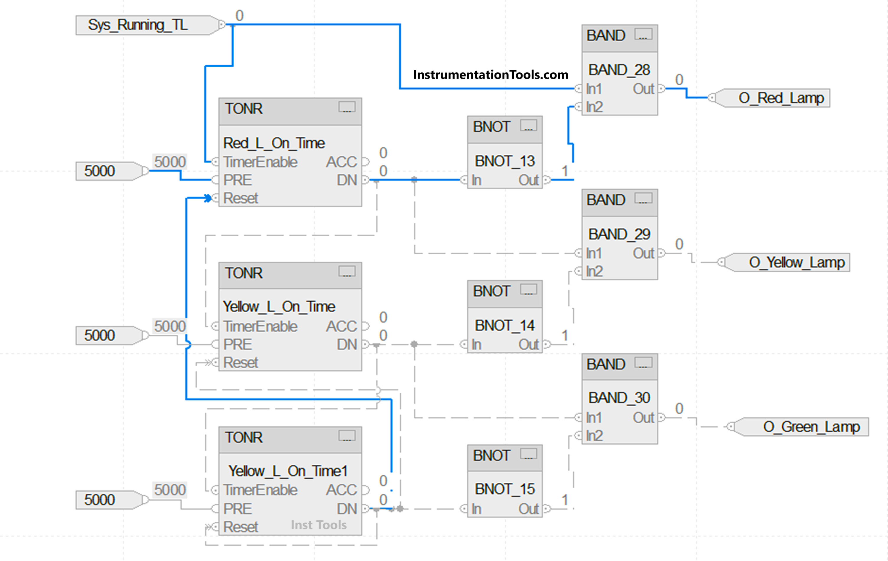
We will use Studio 5000 PLC software for the same. Following are the PLC outputs – red lamp, yellow lamp and green lamp. Refer to the below image for the logic written.
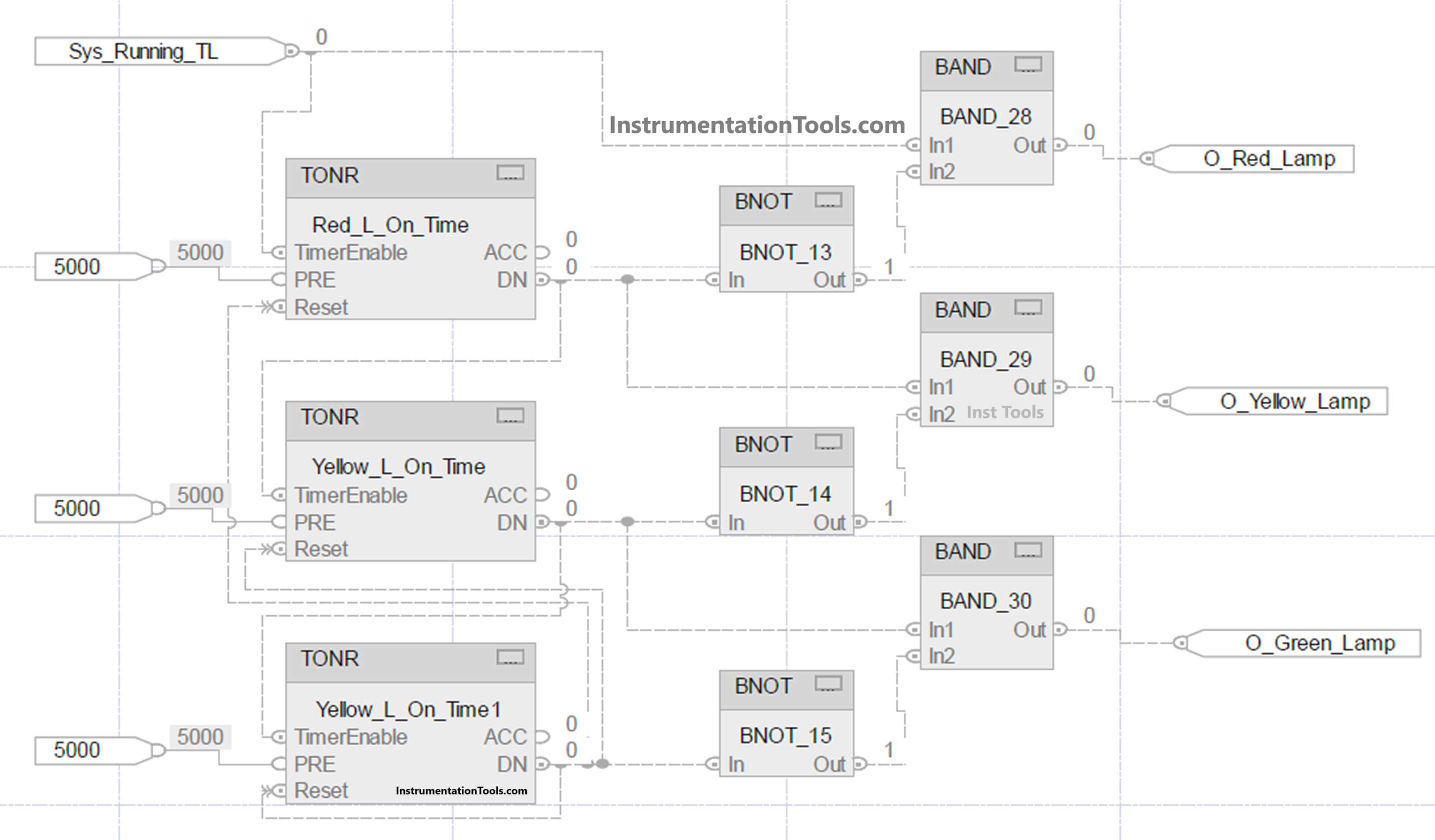
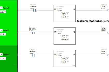
We will first write the PLC logic for the red lamp. Refer to the below image (in blue lines). The logic written is very simple. We are using TONR block, which allows the timer to reset forcefully. This is the main advantage of Studio 5000 software.
When the system is running, the red lamp turns on. It remains on till 5 seconds have not been completed. Once done, the output turns off.
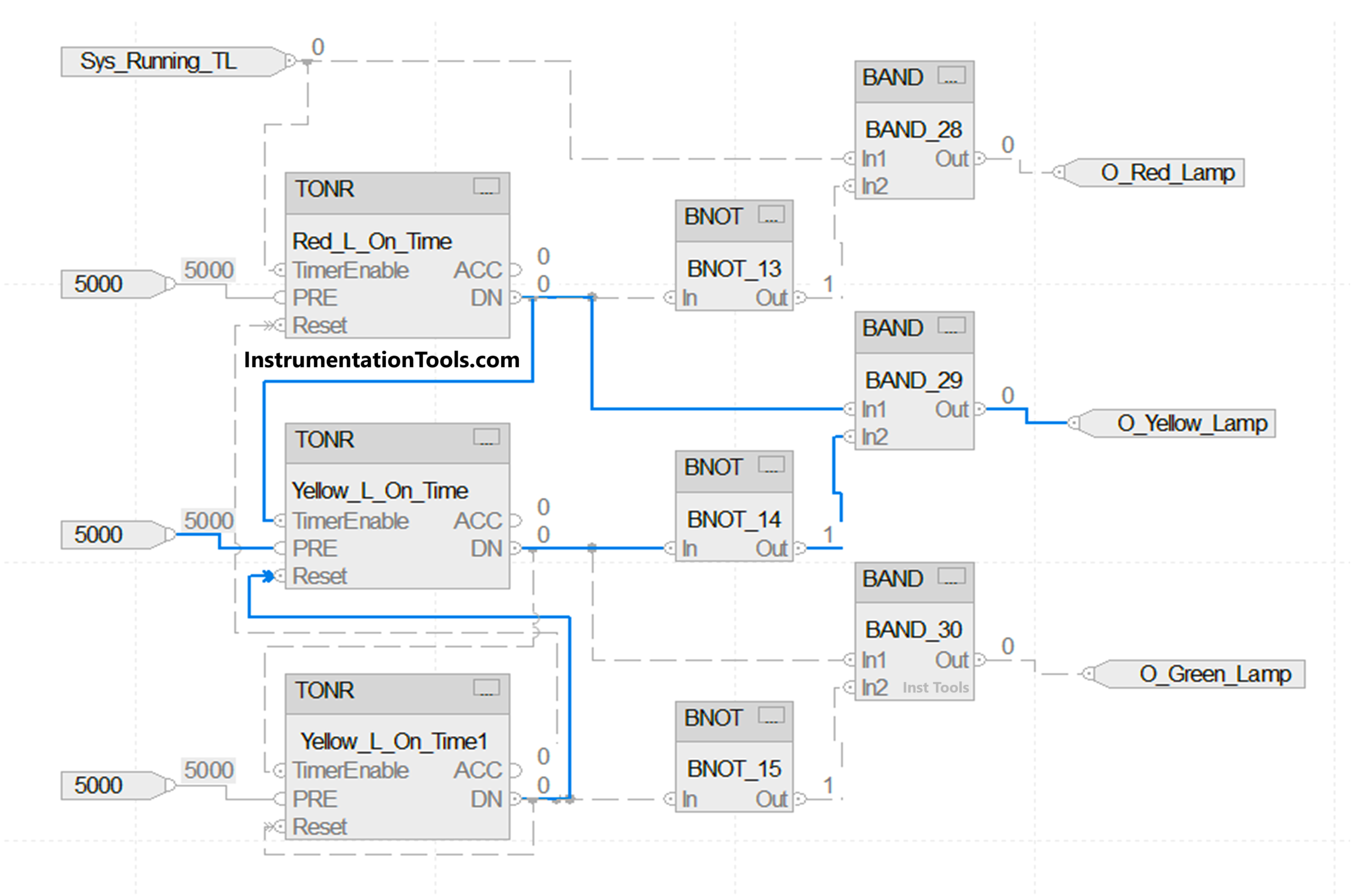
We will next write the logic for the yellow lamp. Refer to the below image (in blue lines). The logic written is very simple. We are using TONR block, which allows the timer to reset forcefully.
When the system is running and the red lamp timer has been completed, the yellow lamp turns on. It remains on till 5 seconds have not been completed. Once done, the output turns off.
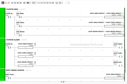
We will next write the logic for the green lamp. Refer to the below image (in blue lines). The logic written is very simple. We are using TONR block, which allows the timer to reset forcefully. When the system is running and the yellow lamp timer has been completed, the green lamp turns on. It remains on till 5 seconds have not been completed. Once done, the output turns off.
After the green lamp timer has been completed, the output of this timer is linked to the reset pins of all the timers. Due to this, the timer will reset and the sequence will start once again. In any case, if the system stops, then all the outputs and timers will become zero. This was solely possible due to TONR blocks, which made it easy to function.
In this way, we saw how to write a PLC program for traffic light sequences using a functional block diagram.
Read Next:
- Light Sequences Structured Text PLC Program
- Simple Conveyor Control PLC Program Example
- Anti-static Wrist Straps in Industrial Automation
- Basic PLC Conveyor System for Product Handling
- PLC based 4 Way Traffic Light Control System