This article will discuss a gas monitoring system with a level indicator using an Omron PLC program. This PLC system aims to monitor gas levels in a room and provide safety warnings. The system will have three levels: Normal, Medium, and Danger. At each level, the system will take specific actions. This PLC system will use a data comparison concept to determine actions for each gas level change.
Program Objective
Step-step Gas Detection System:
- The system has 3 gas level limits: Normal, Medium, and Danger.
- The system has an alarm indicator for each level.
- The setpoint of each level can be adjusted.
- When in the Normal level, the green lamp turns on and the exhaust fan turns off.
- When in the Medium level, the orange lamp and the exhaust fan turn on.
- When in the Danger level, the red lamp turns on, and both the exhaust fan and water sprinkler activate.
Gas Level Monitoring and Alarming
IO Mapping
| S.No. | Comment | Input (I) | Output (Q) | Memory Bit | Memory Word |
|---|---|---|---|---|---|
| 1 | START | 0.00 | |||
| 2 | STOP | 0.01 | |||
| 3 | GREEN_LAMP | 100.00 | |||
| 4 | ORANGE_LAMP | 100.01 | |||
| 5 | RED_LAMP | 100.02 | |||
| 6 | EXHAUST_FAN | 100.03 | |||
| 7 | SPRINKLE | 100.04 | |||
| 8 | PV_GAS | D0 | |||
| 9 | SV_NORMAL | D1 | |||
| 10 | SV_MEDIUM | D2 | |||
| 11 | SV_DANGER | D3 | |||
| 12 | SYSTEM_ON | W0.00 |
PLC Program
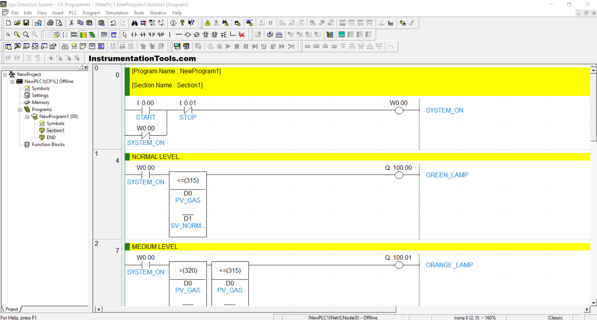
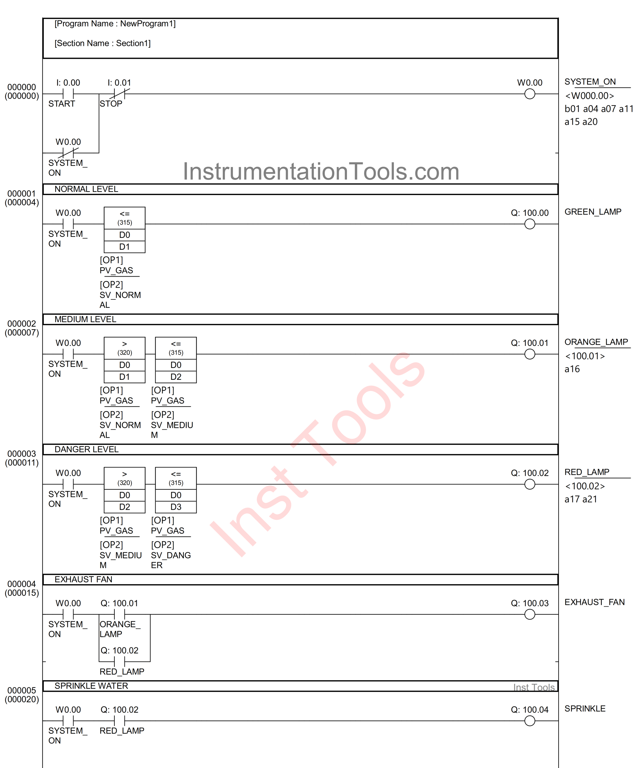
RUNG 0
In this Rung, if the START (0.00) button is pressed, then the memory bit SYSTEM_ON (W0.00) will be in a HIGH state. Because it uses Latching, the memory bit SYSTEM_ON (W0.00) will remain in a HIGH state even though the PB_START (0.00) button has been released.
The memory bit SYSTEM_ON (W0.00) will return to a LOW state if the STOP (0.01) button is pressed.
RUNG 1 (NORMAL LEVEL)
In this Rung, when the NO contact of the memory bit SYSTEM_ON (W0.00) is in a HIGH state and the value in the memory words PV_GAS (D0) is Less Than Or Equal To SV_NORMAL (D1), then the GREEN_LAMP (100.00) output will be ON.
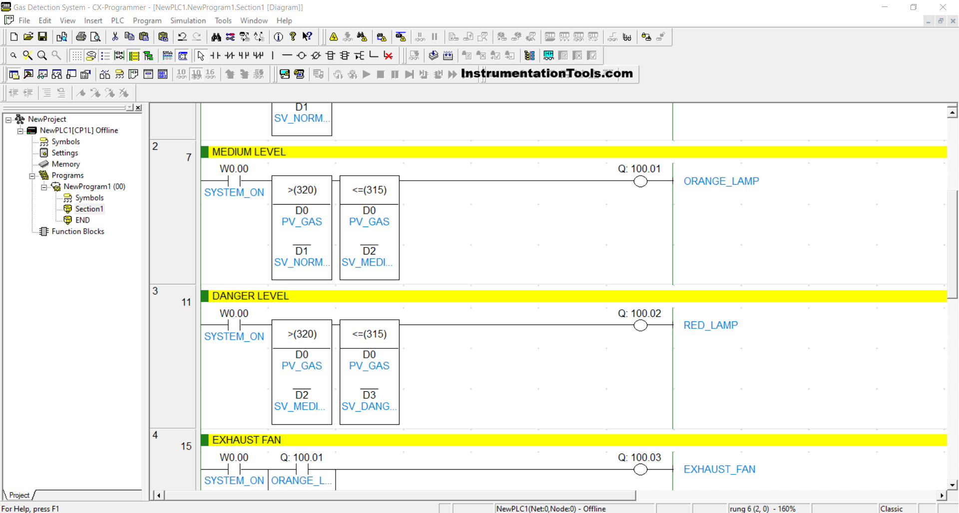
RUNG 2 (MEDIUM LEVEL)
When the NO contact of the memory bit SYSTEM_ON (W0.00) is in the HIGH state and the value of the memory words PV_GAS (D0) is Greater Than SV_NORMAL (D1) and Less Than Or Equal To SV_MEDIUM (D2), the ORANGE_LAMP (100.01) output will be ON.
RUNG 3 (DANGER LEVEL)
When the NO contact of the memory bit SYSTEM_ON (W0.00) is in the HIGH state and the value of memory words PV_GAS (D0) is Greater Than SV_MEDIUM (D2) and Less Than Or Equal To SV_DANGER (D3), the RED_LAMP (100.02) output will be ON.
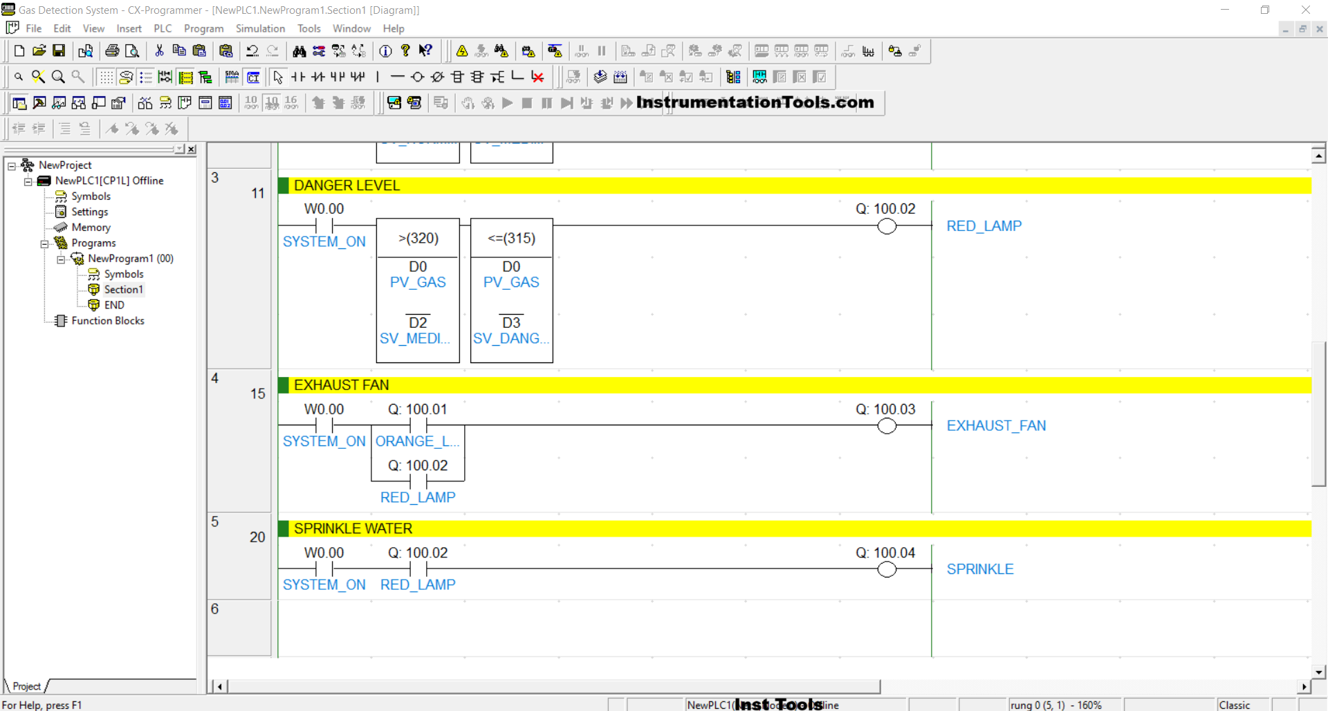
RUNG 4 (EXHAUST FAN)
In this rung, when the NO contact of the memory bit SYSTEM_ON (W0.00) and either the NO contact of ORANGE_LAMP (100.01) or RED_LAMP (100.02) are in a HIGH state, the output EXHAUST_FAN (100.03) will turn ON.
RUNG 5 (SPRINKLE WATER)
In this Rung, when the NO contact of the memory bit SYSTEM_ON (W0.00) and RED_LAMP (100.02) are in the HIGH state, then the SPRINKLE (100.04) output will be ON.
Read Next:
- How to Create Templates in FactoryTalk View Studio?
- PLC Program to Mix 4 Materials with Time and Weight Control
- Control Algorithms in PLC Programming Explained with Example
- Omron PLC Programming for 4 Conveyor Interlock System
- Single-acting Cylinder OR Logic Operation (PLC and Sensors)