This is a PLC Program for an automatic door control system. Learn PLC programming with example problems for students.
Problem Description
Implement logic for the automatic door open & close system in PLC using ladder diagram programming language.
We will use PLC S7-300 for this application. Also we will use TIA portal software for programming.
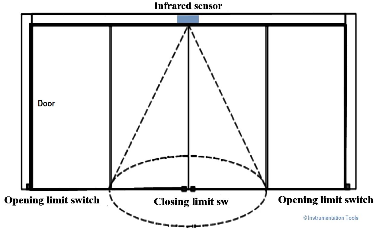
In this system when someone enters the infrared sensing field, opening motor starts working to open the door automatically till the door touches the door opening limit switch.
If the door touches the opening limit switch for 8sec and no body enters the sensing field/area, then closing motor starts to close the door automatically till the door touches the closing limit switch.
Stop the closing action immediately if someone enters the sensing field during the door closing process.
For this application we used S7-300 PLC and TIA portal software for programming.
When infrared sensor is detected (I0.0), door opening motor (Q0.0) will start. The door will be open. When it touches the close limit switch (I0.1), opening motor will be stop.
When the door touches the opening limit switch (I0.2), timer will be executed.
After 8sec time closing motor (Q0.1) will start. When it touches the closing limit switch, closing motor (Q0.1) will turn OFF.
Note :- Above application may be different from actual application. This example is only for explanation purpose only. We can implement this logic in other PLC also. This is the simple concept of automatic door open and close application, we can use this concept in other examples also.
All parameters considered in example are for explanation purpose only, parameters may be different in actual applications. Also all interlocks are not considered in the application.
If you liked this article, then please subscribe to our YouTube Channel for PLC and SCADA video tutorials.
You can also follow us on Facebook and Twitter to receive daily updates.
Read Next:
Omron PLC logic for sorting the number of products and counting the number of products…
Learn the water fountain control logic using the PLC timers programming to control the high…
Open Telemetry is a framework for collecting data in cloud-native applications including tracing, metrics, and…
This article is about controlling the Pneumatic cylinder and Pneumatic motor in the assembly line…
In this post, we will learn the basic requirements for a network switch to be…
The PLC panel and MCC panel interface signals are start, stop, run feedback, trip, local…


View Comments
Plc based ac motor control system
Please give this project