Inst ToolsInst ToolsInst Tools
  • Courses
  • Videos
  • Q & A
    • Interview
      • Instrumentation
      • Electronics
      • Electrical
      • Practical Questions
    • MCQ
      • Instrumentation MCQ
      • Electrical MCQ
      • Electronics MCQ
      • Control Systems MCQ
      • Analog Electronics MCQ
      • Digital Electronics MCQ
      • Power Electronics MCQ
      • Microprocessor MCQ
      • Multiple Choice Questions
  • EE
    • Electronics
      • Electronics Q & A
      • Electronic Basics
      • Electronic Devices & Circuits
      • Electronics Animation
      • Digital Electronics
    • Electrical
      • Electrical Basics
      • Electrical Q & A
      • Power Electronics
      • Electrical Machines
      • Electrical Animation
      • Power Systems
      • Switchgear & Protection
      • Transmission & Distribution
  • Measure
    • Control Valves
    • Calibration
    • Temperature
    • Pressure
    • Flow
    • Level
    • Analyzers
    • Switches
    • Vibration
    • Solenoid Valve
  • Control
    • PLC Tutorials
    • Control Systems
    • Safety Instrumented System (SIS)
    • Communication
    • Fire & Gas System
  • More
    • Design
    • Tools
    • Animation
    • Basics
    • Formulas
    • Standards
    • TextBooks
    • Common
    • Software
    • Excel Tools
    • Erection & Commissioning
    • Process Fundamentals
    • Videos
    • Books
Search
All rights reserved. Reproduction in whole or in part without written permission is prohibited.
Reading: PLC Ladder Program for Automatic Car Wash using Siemens TIA Portal
Share
Notification Show More
Font ResizerAa
Inst ToolsInst Tools
Font ResizerAa
  • Courses
  • PLC Tutorials
  • Control Systems
Search
  • Courses
  • Videos
  • Q & A
    • Interview
    • MCQ
  • EE
    • Electronics
    • Electrical
  • Measure
    • Control Valves
    • Calibration
    • Temperature
    • Pressure
    • Flow
    • Level
    • Analyzers
    • Switches
    • Vibration
    • Solenoid Valve
  • Control
    • PLC Tutorials
    • Control Systems
    • Safety Instrumented System (SIS)
    • Communication
    • Fire & Gas System
  • More
    • Design
    • Tools
    • Animation
    • Basics
    • Formulas
    • Standards
    • TextBooks
    • Common
    • Software
    • Excel Tools
    • Erection & Commissioning
    • Process Fundamentals
    • Videos
    • Books
Follow US
All rights reserved. Reproduction in whole or in part without written permission is prohibited.
Inst Tools > Blog > PLC Tutorials > PLC Ladder Program for Automatic Car Wash using Siemens TIA Portal

PLC Ladder Program for Automatic Car Wash using Siemens TIA Portal

A PLC ladder program using Siemens TIA portal to implement an automatic car wash process with programmable logic controllers.

Last updated: October 17, 2023 3:42 pm
Editorial Staff
PLC Tutorials
2 Comments
Share
6 Min Read
SHARE

A PLC ladder program using Siemens TIA portal to implement an automatic car wash process with programmable logic controllers.

Contents
Car Wash using Siemens TIA PortalCar Wash PLC Logic ExplanationNetwork 1: Washing ON and OFFNetwork 2: Conveyor Start DelayNetwork 3: Conveyor MotorNetwork 4: Car Washing and BrushingNetwork 5: Car Rinsing LogicNetwork 6: Car Drying LogicNetwork 7: Car Washing Complete

When a car is driven onto the conveyor, a sensor must detect the car to start the washing process automatically through the stages of washing, brushing, rinsing, and drying.

The conveyor motor runs at a set constant speed throughout the process.

Car Wash using Siemens TIA Portal

PLC Ladder Program for Automatic Car Wash

The List of Input and Outputs are mentioned in the below table.

AddressDescriptionIO Type
I0.0StartInput
I0.1StopInput
I0.2Car Entry SensorInput
I0.3Car Washing Stage SensorInput
I0.4Car Rinsing Stage SensorInput
I0.5Car Drying stage SensorInput
I0.6Car Exit SensorInput
M0.0 – M0.4Memory BitsMemory
Q0.0Conveyor MotorOutput
Q0.1 – Q0.2Washer/BrushOutput
Q0.3 – Q0.4RinseOutput
Q1.0 – Q1.1DryerOutput
Q1.3Washing in Progress LightOutput
Q1.4Washing Complete LightOutput

Car Wash PLC Logic Explanation

The car wash PLC program is explained step by step with the ladder logic below.

Network 1: Washing ON and OFF

Car Washing ON and OFF PLC Logic

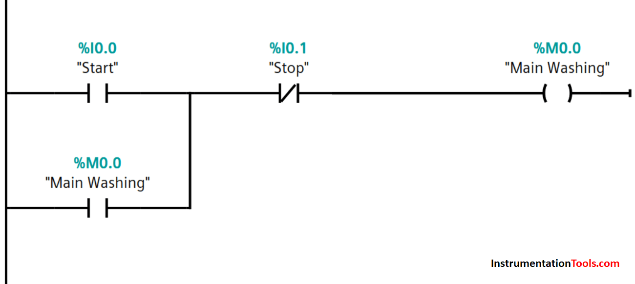
The main control for the start and stop of the car washing process.

Memory bit, M0.0 is set on and off by I0.0 and I0.1 inputs respectively.

Network 2: Conveyor Start Delay

Conveyor Start Delay PLC Program

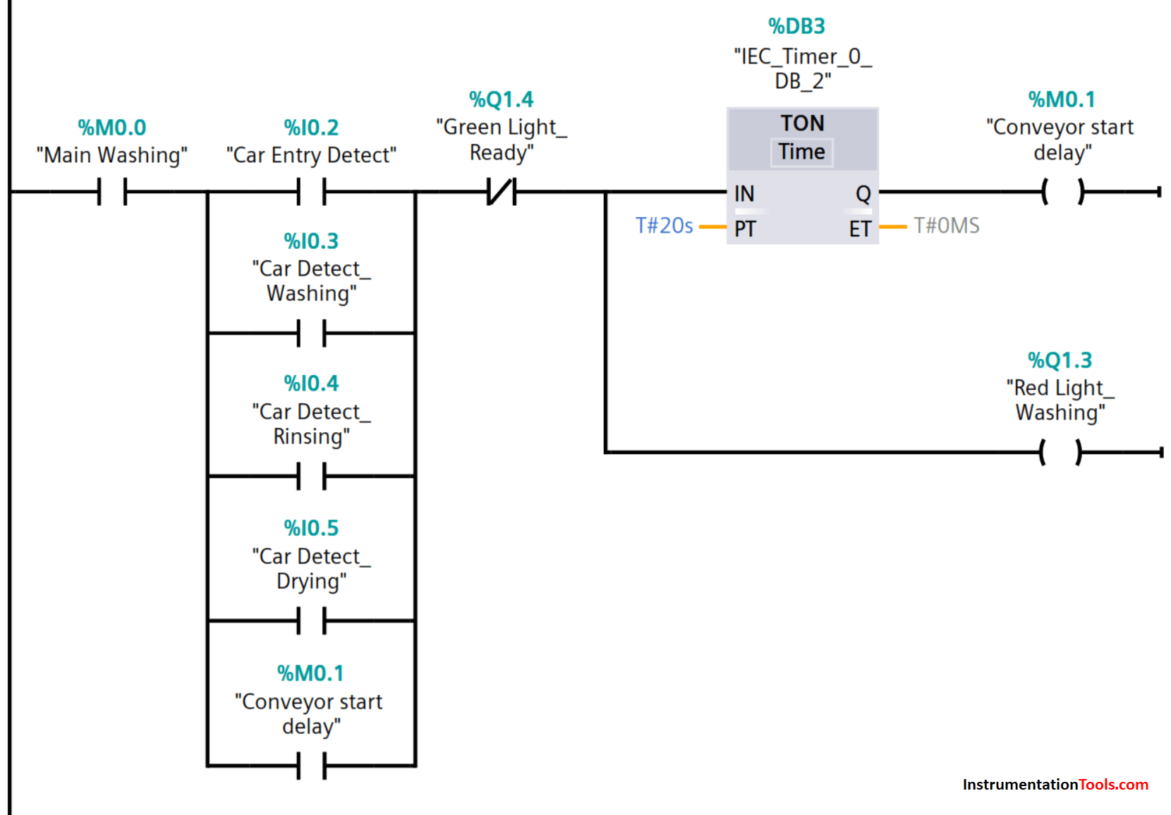
Once a car is driven onto the conveyor, the sensor detects the presence of a car and sets the on-delay timer for the start of the conveyor motor.

Red light also lit up simultaneously to signal washing in progress. At which time, the driver could exit the car before washing begin.

Network 3: Conveyor Motor

PLC Conveyor Motor Code

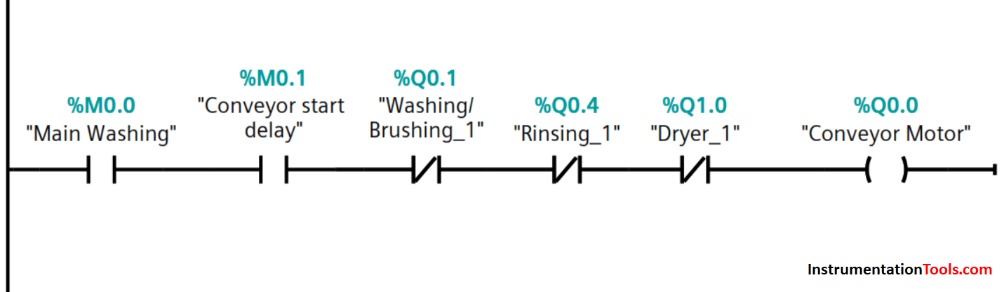
After the elapsed time, the conveyor motor is turned on and moves the car to the washing and brushing stage, and the car entry detection sensor deactivates.

The conveyor is interlocked to stop at washing, rinsing, and drying stages.

Network 4: Car Washing and Brushing

Car Washing and Brushing PLC Program

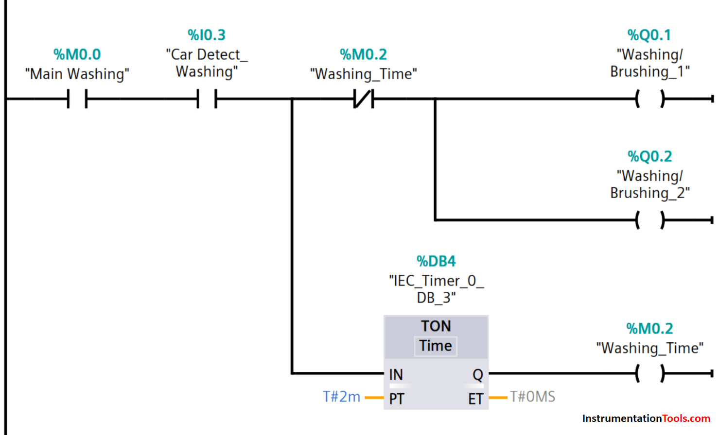
Washing and brushing begin on detection of the car by sensor assigned to input I0.3.

The timing of the washing and brushing stage also begins and lasts for 2 minutes.

After the set time has elapsed, washing and brushing are stopped by M0.2 and the conveyor then moves the car to the rinsing stage.

The washing/brushing stage car detection sensor is deactivated.

Network 5: Car Rinsing Logic

PLC Programming for Car Rinsing

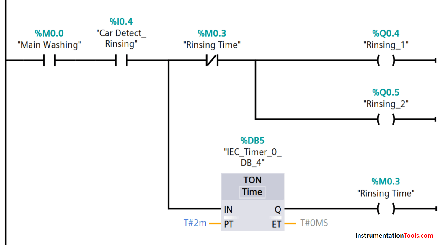
Rinsing begins on detection of the car by sensor assigned to input I0.4.

The timing of the rinsing stage begins and lasts for 2 minutes.

After the set time has elapsed, memory bit M0.3 stops the rinsing and the conveyor moves the car to the drying stage.

The rinsing stage car detection sensor is deactivated.

Network 6: Car Drying Logic

Car Drying Ladder Logic in Tia Portal

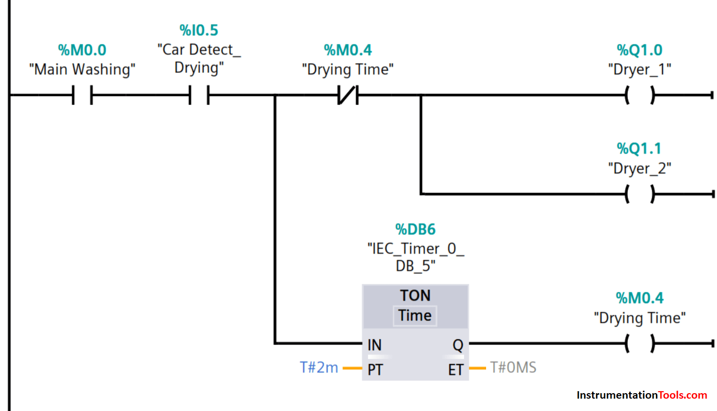
Drying begins on detection of the car by sensor assigned to input I0.5.

The timing of the drying stage also begins and lasts for 2 minutes.

After the set time has elapsed, drying is deactivated by M0.4 and the conveyor moves the car to the exit.

The rinsing stage car detection sensor is deactivated.

Network 7: Car Washing Complete

Car Washing Complete PLC Ladder Diagram

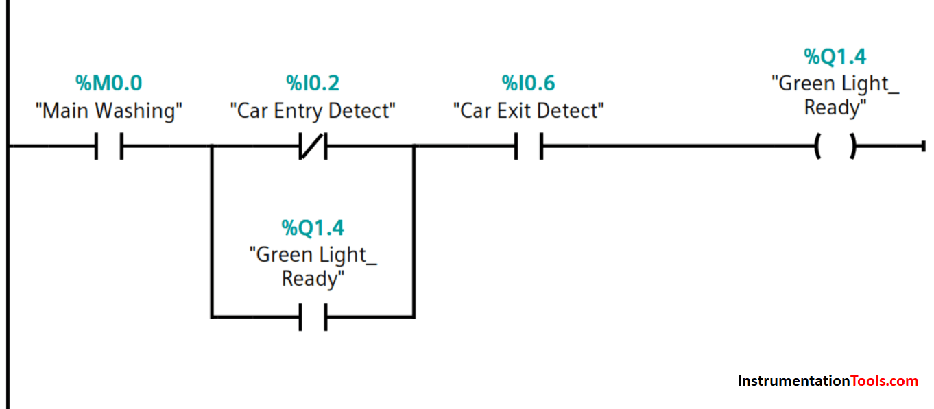
At the exit point, the exit detection sensor is activated and a green light lit up signaling the completion of the car washing process. The conveyor motor stops and the red light goes off.

The car can be driven off and the exit sensor deactivates to make the system ready for the next washing process.

Another car can be driven onto the conveyor and once the entry detection sensor activates, the green light goes off and the red light turns on.

The washing process will then start automatically until the stop button is pressed to halt the whole process.

In case, the process is stopped or interrupted by the operation of the stop button, I0.1, or loss of power, the program will continue from the very stage it was interrupted after restarting.

This is a simplified program. A typical program will incorporate additional inputs and outputs control such as directional control valves, pneumatic cylinders for washing/brushing and rinsing the car tyres, roof, rear, and front parts.

Author: Kweku A. Hagan, TMIET

If you liked this article, then please subscribe to our YouTube Channel for PLC and SCADA video tutorials.

You can also follow us on Facebook and Twitter to receive daily updates.

Read Next:

  • Learn PLC in Hindi
  • PLC Interlock Logic
  • PLC Simulator using Excel
  • SCADA and HMI Systems
  • Yokogawa DCS Architecture
Don't Miss Our Updates
Be the first to get exclusive content straight to your email.
We promise not to spam you. You can unsubscribe at any time.
Invalid email address
You've successfully subscribed !

Continue Reading

Step-by-Step Guide to Choose Right Fuse for a Panel
System and Local Time in PLC
Latched and Momentary Operation of Motor PLC Program
Studio 5000 Tutorial: PLC Programming for Digital Alarms
Automatic Highway Lights Program using RTC in Omron PLC
Basic PLC Exercise on Heater and Cooler for Students
Share This Article
Facebook Whatsapp Whatsapp LinkedIn Copy Link
Share
2 Comments
  • Arjun Sundar says:
    July 26, 2021 at 5:32 pm

    Excellent! Thanks for sharing.

    Reply
  • Arvin Mistry says:
    May 12, 2023 at 10:05 pm

    Excellent do more artiçals
    Thank you

    Reply

Leave a Reply Cancel reply

Your email address will not be published. Required fields are marked *

Stay Connected

128.3kFollowersLike
69.1kFollowersFollow
208kSubscribersSubscribe
38kFollowersFollow

Categories

Explore More

Ladder Logic for Stair-Case wiring using Toggle Switches
PLC Programming Example with Pushbutton and Motor
OB1 – Main Cyclic Organization Block in TIA Portal
Example PLC Program to Control a Pump based on Level Sensors
What is Relay Logic ?
Key Facts About RS485 Industrial Network
What Factors Affect the Choice of PLC Programming Software?
How to implement SR Flip Flop using PLC Ladder Logic
PLC Input Output Modules
What is the OPC Server?

Keep Learning

PLC Technique for IO Mapping

PLC Techniques for I/O Mapping

Garage Door Roller Shutter

Shutter Door Control using Motor and Limit Switches

HMI Screen Design for Hazardous Applications

HMI Screen Design for Hazardous Applications

Indusoft SCADA Modbus Communication

Establishing a Modbus Driver for SCADA Indusoft Web Studio

PROFIBUS is also a Master Slave protocol

Compare Modbus, Fieldbus, and Profibus

Scaling in PLC

How to do Scaling for Analog Input in RSLogix 500?

Analog Inputs in Siemens TIA Portal

What are Analog Inputs? – Analog Signals Processing in PLC

PLC attendance system design

Attendance System PLC Program using CX-Programmer

Discover More

Instrumentation Engineers Interview Questions & Answers

Instrumentation Engineers Interview Questions & Answers

What is a Memristor

What is a Memristor? Principle, Advantages, Applications

Time Response Analysis

Effect of Adding a Zero to a System – II

Design Logic Diagrams with Standard Formats for Process Control

Design Logic Diagrams with Standard Formats for Process Control

Types of Power Electronic Devices

Power Electronic Devices Specification and Classification

Inverse Transducers Objective Questions

Inverse Transducers Objective Questions

2 wire transmitter current loops

2-wire Transmitters Current Loops

Advantages of Three Phase System Compared to Single Phase System

Advantages of Three Phase System Compared to Single Phase System

Follow US
All rights reserved. Reproduction in whole or in part without written permission is prohibited.
Welcome Back!

Sign in to your account

Username or Email Address
Password

Lost your password?