Inst ToolsInst ToolsInst Tools
  • Courses
  • Automation
    • PLC
    • Control System
    • Safety System
    • Communication
    • Fire & Gas System
  • Instrumentation
    • Design
    • Pressure
    • Temperature
    • Flow
    • Level
    • Vibration
    • Analyzer
    • Control Valve
    • Switch
    • Calibration
    • Erection & Commissioning
  • Interview
    • Instrumentation
    • Electrical
    • Electronics
    • Practical
  • Q&A
    • Instrumentation
    • Control System
    • Electrical
    • Electronics
    • Analog Electronics
    • Digital Electronics
    • Power Electronics
    • Microprocessor
  • Request
Search
  • Books
  • Software
  • Projects
  • Process
  • Tools
  • Basics
  • Formula
  • Power Plant
  • Root Cause Analysis
  • Electrical Basics
  • Animation
  • Standards
  • 4-20 mA Course
  • Siemens PLC Course
Reading: PLC FBD Program for Bottle’s Capping with Rotating Mechanism
Share
Notification Show More
Font ResizerAa
Inst ToolsInst Tools
Font ResizerAa
  • Courses
  • Design
  • PLC
  • Interview
  • Control System
Search
  • Courses
  • Automation
    • PLC
    • Control System
    • Safety System
    • Communication
    • Fire & Gas System
  • Instrumentation
    • Design
    • Pressure
    • Temperature
    • Flow
    • Level
    • Vibration
    • Analyzer
    • Control Valve
    • Switch
    • Calibration
    • Erection & Commissioning
  • Interview
    • Instrumentation
    • Electrical
    • Electronics
    • Practical
  • Q&A
    • Instrumentation
    • Control System
    • Electrical
    • Electronics
    • Analog Electronics
    • Digital Electronics
    • Power Electronics
    • Microprocessor
  • Request
Follow US
All rights reserved. Reproduction in whole or in part without written permission is prohibited.
Inst Tools > Blog > PLC Tutorials > PLC FBD Program for Bottle’s Capping with Rotating Mechanism

PLC FBD Program for Bottle’s Capping with Rotating Mechanism

Learn how to write a PLC FBD program for bottle’s capping with a rotating mechanism using a functional block diagram.

Last updated: October 25, 2024 11:01 pm
Viral Nagda
PLC Tutorials
No Comments
Share
7 Min Read
SHARE

Bottle capping system is an application of machine automation. The bottle capping is used to cap the bottles quickly in a short time and takes the production factor as very critical. The PLC program written for such applications must be quick and efficient to cap the bottles precisely. This is because precision and accuracy play a very important role here.

Contents
Bottle’s Capping with Rotating MechanismPLC FBD Program

The program must be written in such a way that there should be no lag or delay in execution, as the system is fast. Otherwise, the machine will fail in operation. In this post, we will write the PLC program for bottle’s capping with a rotating mechanism using a functional block diagram.

Bottle’s Capping with Rotating Mechanism

Let us understand the case scenario first. Refer to the below image. We have a rotating cylinder in the mechanism which is used to rotate the bottles as they come. A sensor will first sense the bottle. If the bottle is not sensed for 20 seconds, then the cylinder will stop.

As soon as it is sensed, it will start again. Now, once the bottle has been mounted on the cylinder, there are two sensors kept aside on the cylinder assembly, one for putting the cap and the other for capping the cap tightly.

When capping is sensed for tightening action, the cylinder will stop for 2 seconds to allow the process to be done. When done, the cylinder will start again and throw the bottle out, indicating that it is done. And the cycle repeats for the next bottle.

Now, there are two things to note during the capping process – when the bottle is sensed for the first time to put on the cap, then the first cap motor will turn on for 1 second after 1 second to put the cap on the moving cylinder; and when the bottle is sensed for the second time to tighten the cap, then the cylinder will turn off after 1 second and the second capping motor will turn on to tighten the cap for 1.5 seconds.

Bottle’s Capping with Rotating Mechanism

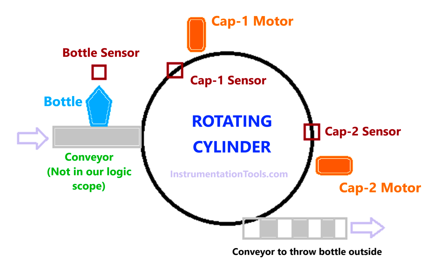
After 2 seconds (starting from the instant when it is turned off) as discussed earlier, the cylinder will start again. Also, when the cylinder is off due to cap-2 sensor sensing, the incoming conveyor will turn off (we will just give a soft signal as the conveyor is not in our control).

PLC FBD Program

Let us write the logic for this now. We will use Studio 5000 software and write the program in functional block diagram language.

Following are the PLC inputs – bottle sensor, cap-1 sensor, and cap-2 sensor.

Following are the PLC outputs – rotating cylinder, cap-1 motor, and cap-2 motor.

Following are the PLC soft signals – incoming conveyor off when cap-2 is in operation.

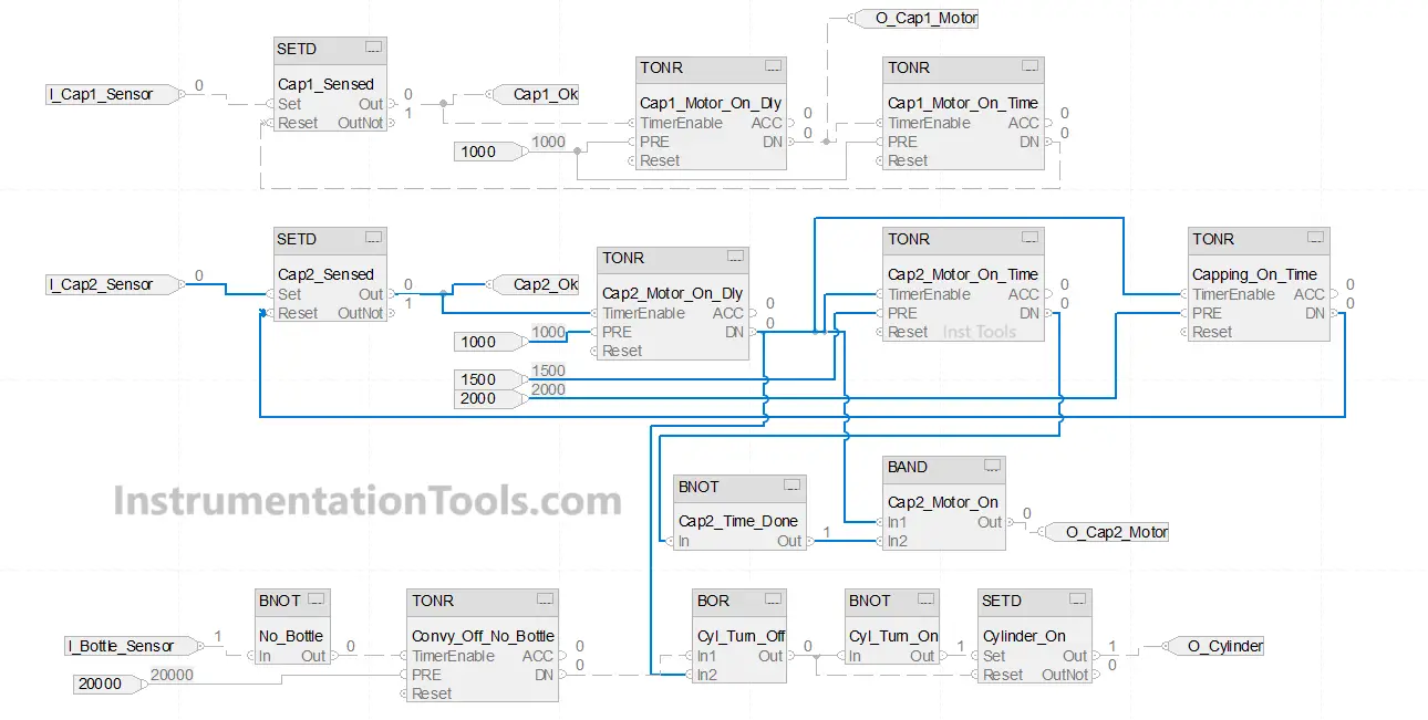
Refer to the below image for the logic written. We have written the logic in three parts – one for the cylinder, one for the cap-1 motor, and one for the cap-2 motor.

PLC FBD Program for Bottle’s Capping with Rotating Mechanism

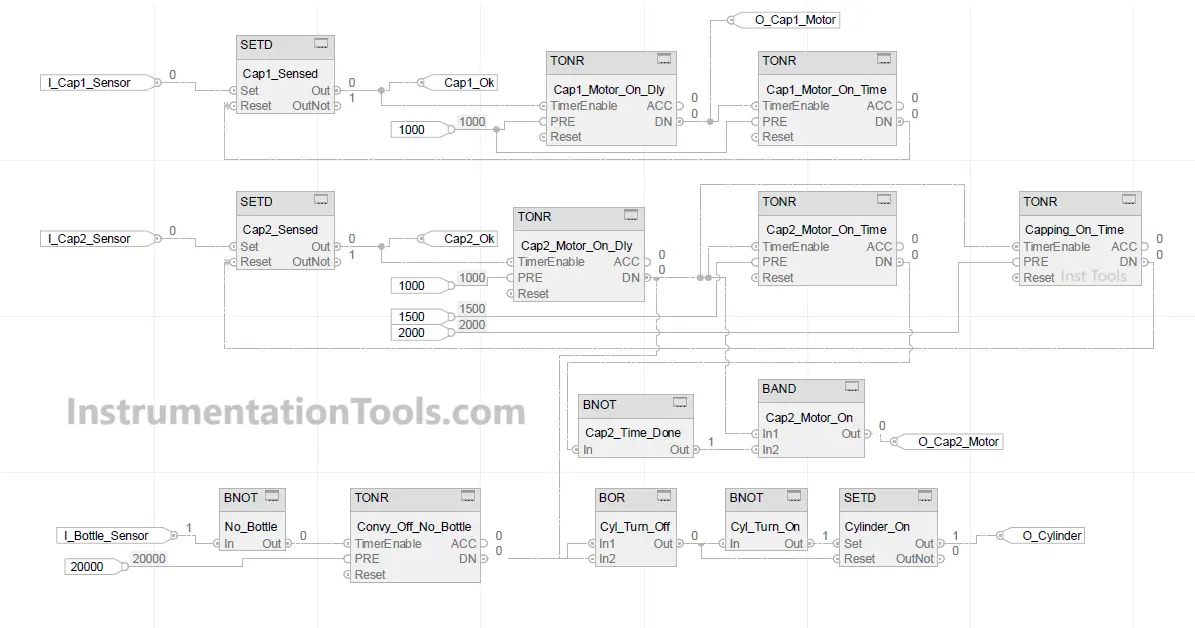
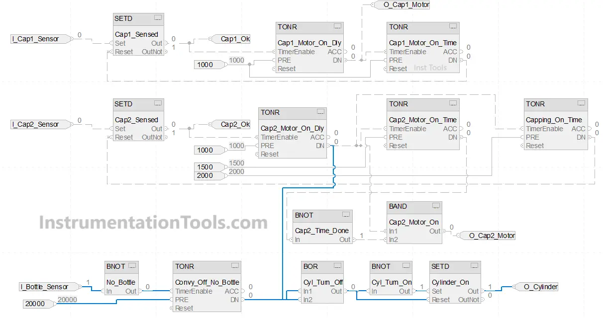
We will first write the logic for the cylinder. Refer to the below image. The blue lines indicate the logic written for the cylinder. When the bottle is not sensed, we use a NOT block to turn on a timer of 20 seconds. Once done, the timer is linked to an OR block which is used to reset the bit O_Cylinder.

Also, if the cap-2 motor on delay of 1 second is completed, then the cylinder will turn off as it is linked to the OR block. When both conditions are off, the output of the OR block is linked to the NOT block which sets the cylinder output.

We use the SETD block here. In this block, there are two inputs – set and reset. If the set bit is high, then the output is set. If the reset bit is high, then the output is reset, on the condition that the set input is not high. It means set input is given priority over reset input.

How to Create a PLC FBD Program for Automated Bottle Capping

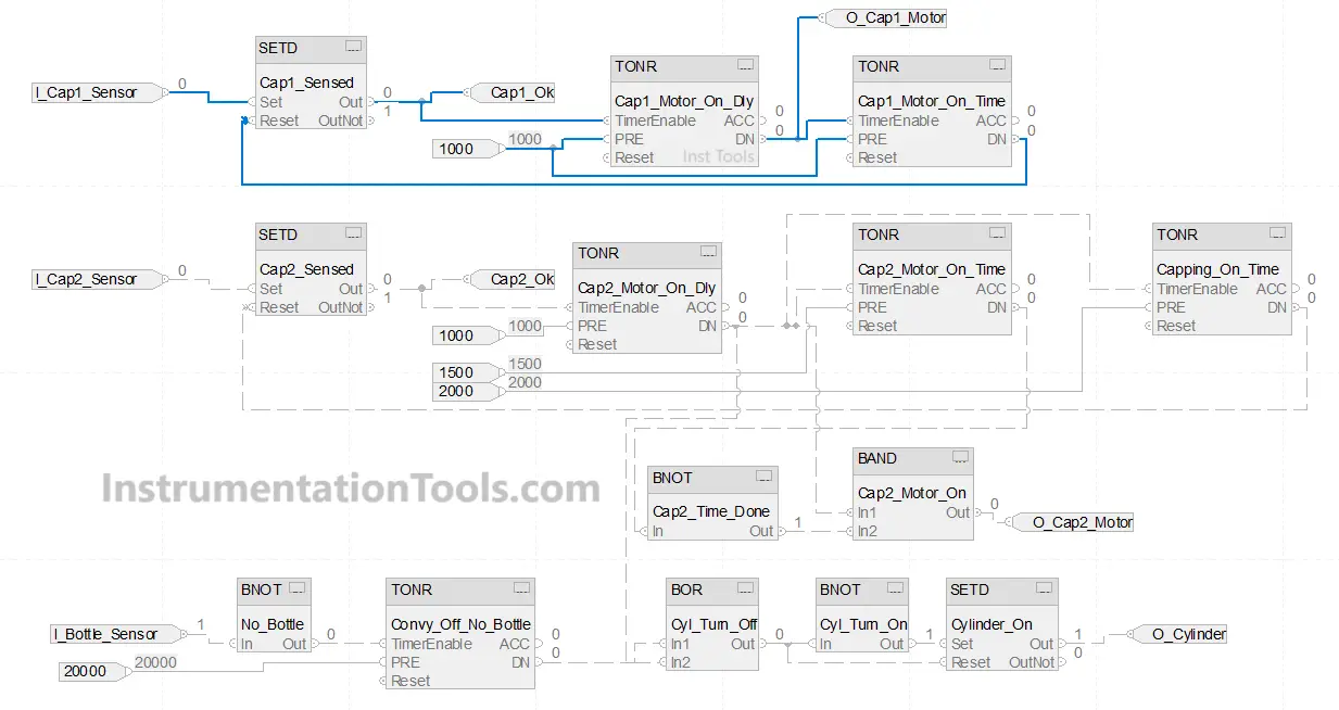
Next, we write the logic for the cap-1 motor. When the cap-1 sensor turns on, we set a bit named cap1_ok and turn on a timer of 1 second which is the delay for the cap-1 motor.

After that timer, we turn on a timer of 1 second which keeps the cap-1 motor (O_Cap1_Motor) on at that time. Once done, the output is linked back to the reset condition of cap1_ok.

PLC Programming for Rotating Bottle Capping

Next, we write the logic for the cap-2 motor. When the cap-2 sensor turns on, we set a bit named cap2_ok and turn on a timer of 1 second which is the delay for the cap-2 motor.

After that timer, we turn on a timer of 1.5 seconds which keeps the cap-2 motor (O_Cap2_Motor) on at that time. Parallely, we also turn on a timer of 2 seconds which keeps the cylinder off at that time.

Once the timer of 1.5 seconds is done, the output of the cap-2 motor turns off and once the timer of 2 seconds is done, the output is linked back to the reset condition of cap2_ok.

Bottle Capping Automation with PLC

In this way, we saw how to write a PLC program for bottle’s capping with a rotating mechanism using a functional block diagram.

Read Next:

  • PLC Tank Liquid Heating Control by Steam Flow
  • System architecture and process control Design
  • Anti-static Wrist Straps in Industrial Automation
  • FBD Program for Burglar Alarm Security System
  • Functional Block Diagram for Traffic Lights Logic
Don't Miss Our Updates
Be the first to get exclusive content straight to your email.
We promise not to spam you. You can unsubscribe at any time.
Invalid email address
You've successfully subscribed !

Continue Reading

PLC Programming for Weight-Based Packaging
How to Create Faceplate in FactoryTalk View Studio?
Quiz: Identifying I/O Examples in PLC Systems
Structured Text in PLC: Parking Information Systems
Emergency Stop Switch Spurious Trip
PLC Programming Example on Multi-Motor Control for Beginners
Share This Article
Facebook Whatsapp Whatsapp LinkedIn Copy Link
Share
Leave a Comment

Leave a Reply Cancel reply

Your email address will not be published. Required fields are marked *

Stay Connected

128.3kFollowersLike
69.1kFollowersFollow
210kSubscribersSubscribe
38kFollowersFollow

Categories

Explore More

PLC Program for Paint Spraying
PLC Program for Conditional Control Logic
Difference between PLC and Computers
Ladder Logic Example with Timers
PUT Command in Siemens PLC – TIA Portal Basics
What is the Firmware Version of a PLC? – Siemens PLC Hardware
PLC Program for Two Way Switch Logic
Move, Move Bit, Move Digit – Examples of Omron PLC Programs

Keep Learning

Shift Bit Register in PLC

Shift Bit Register in PLC

Workstation Healthiness Checks

Workstation Healthiness Checks

PLC program for bread oven

Bread Oven Control in Auto and Manual Modes PLC Program

Basic PLC Alarm Programming Example

Basic PLC Alarm Programming Example

Simulator in S7-1200 and S7-1500 PLC

How to Work With Simulator in S7-1200 and S7-1500 PLC?

Face Mask Making Machine using PLC and HMI

Face Mask Making Machine using PLC and HMI

Difference Between SCADA and HMI

Difference Between SCADA and HMI

Cyclic Interrupts TIA Portal

Configuring and Usage of Cyclic Interrupts TIA Portal (OB 30+)

Learn More

Linear Programming in Excel

How to Do Linear Programming in Excel?

Float level gauge Principle

Float Type Level Indicator Principle

Burner Management System (BMS) Principle

What is Burner Management System (BMS)?

DC Motor Connections

DC Motor Connections

Group of Induction Motors

How to Operate a Group of Induction Motors using PLC Logic?

PLC Battery

Everything You Need to Know About PLC Battery

Direct Acting Actuators

Effect of Differential Pressure on Control Valve Lift

100 Digital Electronics and Microprocessor Questions for Practice Exam

100 Digital Electronics and Microprocessor Questions for Practice Exam

Menu

  • About
  • Privacy Policy
  • Copyright

Quick Links

  • Learn PLC
  • Helping Hand
  • Part Time Job

YouTube Subscribe

Follow US
All rights reserved. Reproduction in whole or in part without written permission is prohibited.
Welcome Back!

Sign in to your account

Username or Email Address
Password

Lost your password?