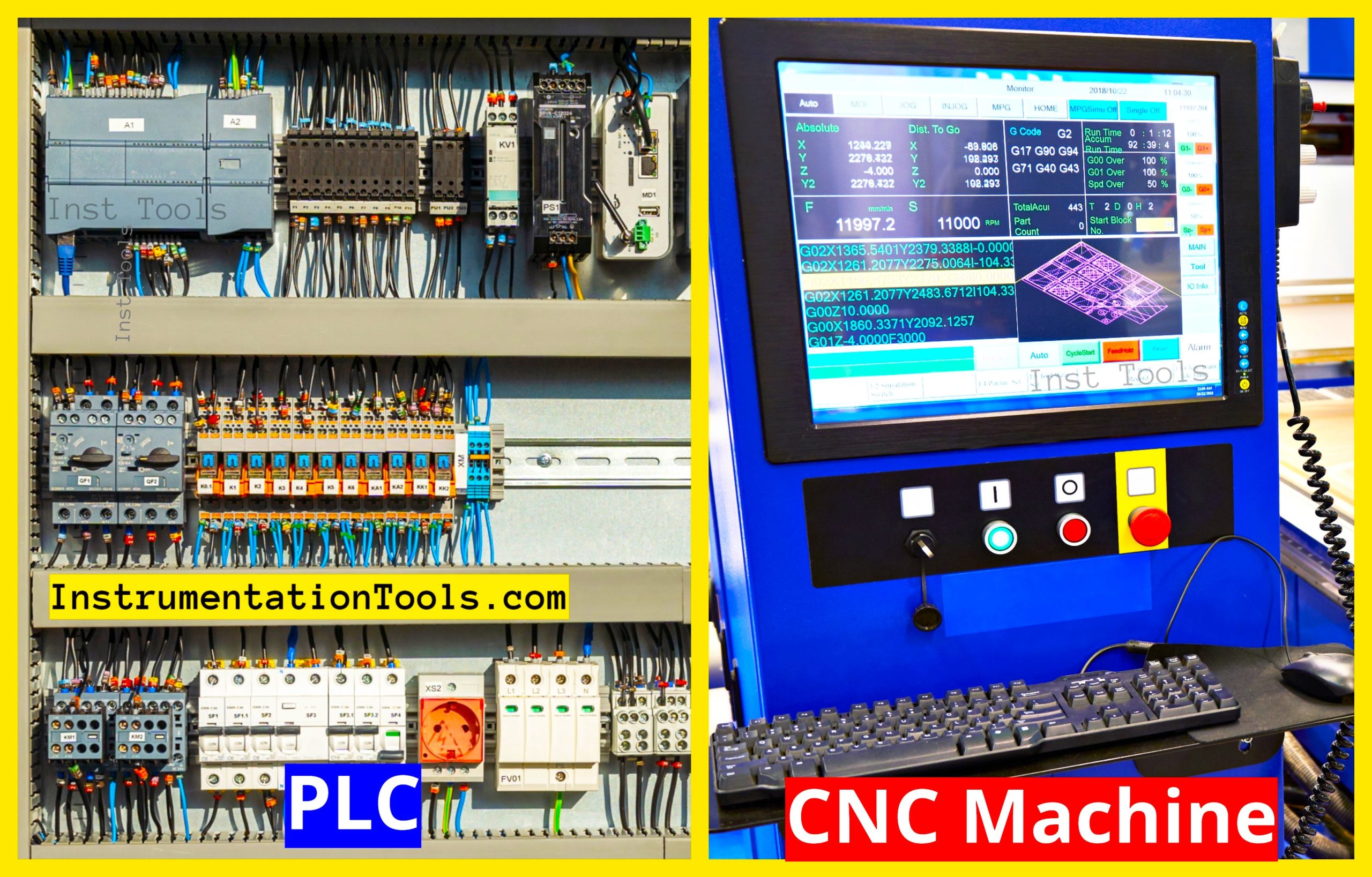
When you are looking to automate your application in an industry, there are no other best choices apart from PLC or CNC machines.
Today, they have revolutionized the manufacturing industry with such a rapid level of efficiency, productivity, and reliability. There are two major categories of controllers used in industries. Though both are automatic in operation, they have a wide level of differences between them.
In this post, we will discover the key differences between PLC and CNC machines in the manufacturing industry. Learn unique features and benefits of automation.
What is PLC?
PLC stands for programmable logic controller. PLC is a type of device which is a combination of both software and hardware. This means you can wire and interface various types of sensors, instruments, valves, actuators, and other types of devices with it; and at the same time, program it with a code for making the logic function. PLC consists of the following parts – a power supply, CPU, memory storage, input module, output module, communication port, and programming port.
The PLC is powered by 24V AC/DC or 230V AC. This is the standard power supply required for a PLC. The processor does all the logic work where the program written by the programmer is executed. The memory storage is used to store data, logic, and variables.
The input module is an embedded system inside a PLC which takes hard input in the form of an electrical voltage (mostly 24V DC) from sensors and other field equipment and converts it inside into digital information for processing with the CPU.
The output module is an embedded system inside PLC which converts the digital information and data from the logic written and converts it into an electrical signal in the form of AC or DC voltage, required for various field equipment.
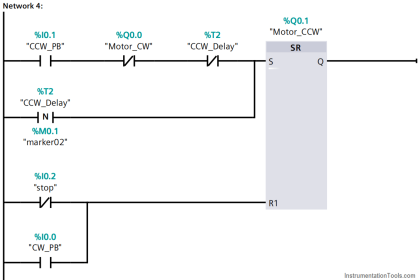
PLC uses five types of programming languages required to control a process – ladder logic, functional block diagram, structured text, instruction list and sequential flow chart.
What is CNC?
CNC stands for computerized numerical control. CNC is a controller which has a CPU inside and performs execution of a logic based on the input received, for controlling a machine process like lathe, mills, and other hardcore jobs.
CNC machines are mostly used in machine automation processes. It can be understood as an integration of PLC and robot, where you can write coding for executing various axes operations (maximum 5 axes) in high precision and accuracy.
Let us understand this simply in terms of its application. You may have seen a screwdriver; it has various sizes of screws in different shapes. When you are manufacturing it, the design of these sizes is fed into a CNC machine, and the machine will automatically recognize it and manufacture the same by moving its mechanical parts in the required axes.
The CNC machine is run by a program called G-code. G-code is a language that guides the cutting tool to achieve accurate measurements for production like Cartesian coordination, tool location, feed rate, and speed. A CNC machine has the following components – input device, processor, machine tool, driving system, display unit, and feedback system.
The input device can be a USB plug, floppy disk, or communication cable. It is used to feed the system with the required input as to what type of design is to be done, in the form of G-code. The processor is used to decode the G-code and execute it for performing the operation on the machine.
Various interpolations like linear, circular, and helical are performed on the axes to control the process. It gives motion commands and also receives feedback to accurately control the process continuously. The driving system can be considered as a device used for moving the mechanical parts, as it is the actual interface between mechanical devices and the controller. It can be some drive motor or ball screw moving part.
The machine tool is the part which performs operation on the load, based on the command received from the driving system. It can be a spindle or slide table, moving in the required axes. The feedback system consists of encoders, speed sensors and position sensors for reading the actual work done and giving it back to the controller for correction in action.
A CNC programmer first designs the required machine type in CAM / CAD and feeds it to the machine for processing through G-code. The CNC machine needs to learn those designs and execute the fed G-code accordingly.
What is the difference between PLC and CNC?
PLC is programmed through languages of ladder logic, functional block diagram, structured text, instruction list and sequential flow chart; whereas CNC is programmed through G-code where it is first designed in CAM / CAD software.
Graphical display in a PLC is optional and based on the design, whereas a CNC machine has compulsorily a graphical display embedded on it.
CNC machines are mostly used for machine automation, whereas PLC is used for all types of automation. A PLC too can perform machine automation through servo drives and stepper drives.
A CNC machine works on only numerical values, as compared to a PLC which works on discrete, analog and high-speed values.
A CNC machine works best for accuracy and precision, but a PLC works for all aspects ranging from when to start/stop, how to control and how to respond to various types of inputs.
Comparison
| PLC (Programmable Logic Controller) | CNC (Computer Numerical Control) Machine |
| PLC controls automation processes in industrial systems | CNC controls the movement of machines to perform precise manufacturing tasks |
| PLC is used in general industrial automation (e.g., process control, assembly) | CNC specifically used in machining operations (e.g., milling, drilling, cutting) |
| PLC programmed using ladder logic, structured text, or FBD | CNC Programmed using G-code or M-code to control machine operations |
| PLC manages real-time control of devices like sensors, actuators, and motors | CNC directs machine tools to cut, shape, or assemble parts based on programmed instructions |
| PLC may include a simple HMI or text-based interface for system control | CNC typically features a detailed interface for machine operation and setup |
| PLC is lower cost (depends on the system complexity) | CNC typically high cost due to precision and specialized equipment |
| PLC – Discrete and analog signals to control industrial equipment | CNC – Numerical control outputs for precise machine movements |
In this way, we saw the difference between PLC and CNC machines.
Read Next:
- CNC Programming – Definition, Types, and Tips
- Ladder Logic MCQ Questions and Answers
- Custom CNC Machining – A Complete Guide
- PLC Techniques for I/O Mapping Procedures
- Steps Followed Before Creating CNC Program