Inst ToolsInst ToolsInst Tools
  • Ask
  • Courses
  • Videos
  • Q & A
    • Interview
      • Instrumentation
      • Electronics
      • Electrical
      • Practical Questions
    • MCQ
      • Instrumentation MCQ
      • Electrical MCQ
      • Electronics MCQ
      • Control Systems MCQ
      • Analog Electronics MCQ
      • Digital Electronics MCQ
      • Power Electronics MCQ
      • Microprocessor MCQ
      • Multiple Choice Questions
  • EE
    • Electronics
      • Electronics Q & A
      • Electronic Basics
      • Electronic Devices & Circuits
      • Electronics Animation
      • Digital Electronics
    • Electrical
      • Electrical Basics
      • Electrical Q & A
      • Power Electronics
      • Electrical Machines
      • Electrical Animation
      • Power Systems
      • Switchgear & Protection
      • Transmission & Distribution
  • Measure
    • Control Valves
    • Calibration
    • Temperature
    • Pressure
    • Flow
    • Level
    • Analyzers
    • Switches
    • Vibration
    • Solenoid Valve
  • Control
    • PLC Tutorials
    • Control Systems
    • Safety Instrumented System (SIS)
    • Communication
    • Fire & Gas System
  • More
    • Design
    • Tools
    • Animation
    • Basics
    • Formulas
    • Standards
    • TextBooks
    • Common
    • Software
    • Excel Tools
    • Erection & Commissioning
    • Process Fundamentals
    • Videos
    • Books
Search
All rights reserved. Reproduction in whole or in part without written permission is prohibited.
Reading: Peak Inverse Voltage of Center Tap Rectifier
Share
Notification Show More
Font ResizerAa
Inst ToolsInst Tools
Font ResizerAa
  • Courses
  • PLC Tutorials
  • Control Systems
Search
  • Ask
  • Courses
  • Videos
  • Q & A
    • Interview
    • MCQ
  • EE
    • Electronics
    • Electrical
  • Measure
    • Control Valves
    • Calibration
    • Temperature
    • Pressure
    • Flow
    • Level
    • Analyzers
    • Switches
    • Vibration
    • Solenoid Valve
  • Control
    • PLC Tutorials
    • Control Systems
    • Safety Instrumented System (SIS)
    • Communication
    • Fire & Gas System
  • More
    • Design
    • Tools
    • Animation
    • Basics
    • Formulas
    • Standards
    • TextBooks
    • Common
    • Software
    • Excel Tools
    • Erection & Commissioning
    • Process Fundamentals
    • Videos
    • Books
Follow US
All rights reserved. Reproduction in whole or in part without written permission is prohibited.
Inst Tools > Blog > Electronic Devices & Circuits > Peak Inverse Voltage of Center Tap Rectifier

Peak Inverse Voltage of Center Tap Rectifier

Last updated: October 4, 2016 1:39 pm
Editorial Staff
Electronic Devices & Circuits
No Comments
Share
1 Min Read
SHARE

Peak Inverse Voltage Each diode in the full-wave rectifier is alternately forward-biased and then reverse-biased. The maximum reverse voltage that each diode must withstand is the peak secondary voltage Vp(sec). This is shown in Figure where D2 is assumed to be reverse-biased (red) and D1 is assumed to be forward-biased (green) to illustrate the concept.

Peak Inverse Voltage of Center Tap Rectifier

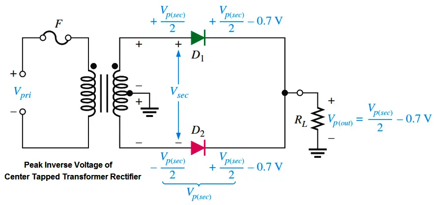
Fig : Diode reverse voltage ( D2 Reverse Biased & D1 Forward Biased )

When the total secondary voltage Vsec has the polarity shown, the maximum anode voltage of D1 is Vp(sec)> 2 and the maximum anode voltage of D2 is -Vp(sec)>2. Since D1 is assumed to be forward-biased, its cathode is at the same voltage as its anode minus the diode drop; this is also the voltage on the cathode of D2.

The peak inverse voltage across D2 is

center-tapped-full-wave-rectifier-piv

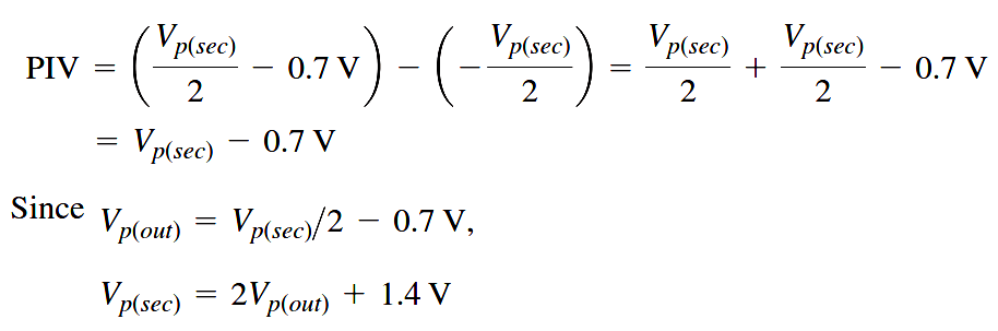
Therefore, by substitution, the peak inverse voltage across either diode in a full-wave center tapped rectifier is

peak-inverse-voltage-formula

Don't Miss Our Updates
Be the first to get exclusive content straight to your email.
We promise not to spam you. You can unsubscribe at any time.
Invalid email address
You've successfully subscribed !
Cathode Ray Tube (CRT)
Methods of Transistor Biasing
Basics of Voltage Regulators
Electronic Symbols
Power MOSFET
Share This Article
Facebook Whatsapp Whatsapp LinkedIn Copy Link
Share
Leave a Comment

Leave a Reply Cancel reply

Your email address will not be published. Required fields are marked *

Stay Connected

128.3kFollowersLike
69.1kFollowersFollow
208kSubscribersSubscribe
38kFollowersFollow

Categories

Recent Comments

  • Guifty Shimica on Top Non-PLC Certification Courses for Automation Professionals
  • Guifty Shimica on Top Non-PLC Certification Courses for Automation Professionals
  • MIHARITSOA Aina Sitraka on Top Non-PLC Certification Courses for Automation Professionals
  • Vaishnavi on Free Instrumentation Course for Trainee Engineers

Related Articles

Transistors Questions & Answers

Transistors Questions & Answers

phototransistor symbols

Phototransistor Working Principle

Fluorescent Screen of CRT

CRT Fluorescent Screen

working-of-pnp-transistor

Working of NPN Transistor

diode-limiter-principle

Diode Limiters/Clippers Operation

Why Silicon is preferred over Germanium ?

Why Silicon is preferred over Germanium ?

zener-diode-as-voltage-regulator

Operation of Zener Diode Voltage Regulator

transistor-terminals

Basics of Transistors

More Articles

How to Connect HART Communicator with DP Transmitter

15 HART Communicator Questions

Ladder Logic Questions and Answers

Ladder Logic MCQ Questions and Answers

progressively sequenced control valves

Progressive Control Valve Sequence

Structured Control Language (SCL) Elements

Value Assignments in SCL Language – Single, Multiple, Combined

SIS System Testing - Safety PLC Control System

SIS System Testing – Safety PLC

Automatic Packing of Bottles

Automatic Packing of Bottles Programming

Stability in Frequency Domain

Feedback Compensation

Pulsed Fluorescence SO2-H2S-CS Analyzer Working Principle

Pulsed Fluorescence SO2, H2S, CS Analyzer Working Principle

Follow US
All rights reserved. Reproduction in whole or in part without written permission is prohibited.
Welcome Back!

Sign in to your account

Username or Email Address
Password

Lost your password?