Of all the pressure-based flow elements in existence, the most common is the orifice plate. This is simply a metal plate with a hole in the middle for fluid to flow through.
Orifice plates are typically sandwiched between two flanges of a pipe joint, allowing for easy installation and removal:
Orifice Plates

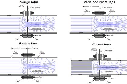
The point where the fluid flow profile constricts to a minimum cross-sectional area after flowing through the orifice is called the vena-contracta, and it is the area of minimum fluid pressure.
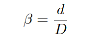
The vena-contracta corresponds to the narrow throat of a venturi tube. The precise location of the vena-contracta for an orifice plate installation will vary with flow rate, and also with the beta ratio (β) of the orifice plate, defined as the ratio of bore diameter (d) to inside pipe diameter (D):
Concentric Orifice Plate
The simplest design of orifice plate is the square-edged, concentric orifice. This type of orifice plate is manufactured by machining a precise, straight hole in the middle of a thin metal plate.
Looking at a side view of a square-edged concentric orifice plate reveals sharp edges (90o corners) at the hole:

Square-edged Orifice Plates
Square-edged orifice plates may be installed in either direction, since the orifice plate “appears” exactly the same from either direction of fluid approach.
In fact, this allows square-edged orifice plates to be used for measuring bidirectional flow rates (where the fluid flow direction reverses itself from time to time).
A text label printed on the “paddle” of any orifice plate customarily identifies the upstream side of that plate, but in the case of the square-edged orifice plate it does not matter.
For example : Here in below image, Label is : INLET

The purpose of having a square edge on the hole in an orifice plate is to minimize contact with the fast-moving moving fluid stream going through the hole. Ideally, this edge will be knife-sharp.
If the orifice plate is relatively thick (1/8 or an inch or more), it may be necessary to bevel the downstream side of the hole to further minimize contact with the fluid stream:

Looking at the side-view of this orifice plate, the intended direction of flow is left-to-right, with the sharp edge facing the incoming fluid stream and the bevel providing a non-contact outlet for the fluid. Beveled orifice plates are obviously uni-directional, and must be installed with the paddle text facing upstream.
square-edged orifice plates
Other square-edged orifice plates exist to address conditions where gas bubbles or solid particles may be present in liquid flows, or where liquid droplets or solid particles may be present in gas flows.
Eccentric Orifice Plate
The first of this type is called the eccentric orifice plate, where the hole is located off-center to allow the undesired portions of the fluid to pass through the orifice rather than build up on the upstream face:

For gas flows, the hole should be offset downward, so any liquid droplets or solid particles may easily pass through. For liquid flows, the hole should be offset upward to allow gas bubbles to pass through and offset downward to allow heavy solids to pass through.
segmental orifice plate
The second off-center orifice plate type is called the segmental orifice plate, where the hole is not circular but rather just a segment of a concentric circle:

As with the eccentric orifice plate design, the segmental hole should be offset downward in gas flow applications and either upward or downward in liquid flow applications depending on the type of undesired material(s) in the flowstream.
Orifice Plate with Vent and Drain Holes
An alternative to offsetting or re-shaping the bore hole of an orifice plate is to simply drill a small hole near the edge of the plate, flush with the inside diameter of the pipe, allowing undesired substances to pass through the plate rather than collect on the upstream side.
If such a hole is oriented upward to pass vapor bubbles, it is called a vent hole. If the hole is oriented downward to pass liquid droplets or solids, it is called a drain hole. Vent and drain holes are useful when the concentration of these undesirable substances is not significant enough to warrant either an eccentric or segmental orifice:

The addition of a vent or drain hole should have negligible impact on the performance of an orifice plate due to its small size relative to the main bore. If the quantity of undesirable material in the flowstream (bubbles, droplets, or solids) is excessive, an eccentric or segmental orifice plate might be a better choice.
Some orifice plates employ non-square-edged holes for the purpose of improving performance at low Reynolds number values, where the effects of fluid viscosity are more apparent. These orifice plate types employ rounded- or conical-entrance holes in an effort to minimize the effects of fluid viscosity.
Experiments have shown that decreased Reynolds number causes the flowstream to not contract as much when traveling through an orifice, thus limiting fluid acceleration and decreasing the amount of differential pressure produced by the orifice plate.
However, experiments have also shown that decreased Reynolds number in a venturi-type flow element causes an increase in differential pressure due to the effects of friction against the entrance cone walls.
By manufacturing an orifice plate in such a way that the hole exhibits “venturi-like” properties (i.e. a dull edge where the fast-moving fluid stream has more contact with the plate), these two effects tend to cancel each other, resulting in an orifice plate that maintains consistent accuracy at lower flow rates and/or higher viscosities than the simple square-edged orifice.
Quadrant-edge orifice plates
Two common non-square-edge orifice plate designs are the quadrant-edge and conical-entrance orifices. The quadrant-edge is shown first:

Conical-entrance orifice plate
The conical-entrance orifice plate looks like a beveled square-edge orifice plate installed backwards, with flow entering the conical side and exiting the square-edged side:

Here, is it vitally important to pay attention to the paddle’s text label. This is the only sure indication of which direction an orifice plate needs to be installed. One can easily imagine an instrument technician mistaking a conical-entrance orifice plate for a square-edged, beveled orifice plate and installing it backward!
If you liked this article, then please subscribe to our YouTube Channel for Electrical, Electronics, Instrumentation, PLC, and SCADA video tutorials.
You can also follow us on Facebook and Twitter to receive daily updates.
Read Next:
- Flow Meter Square root Relationship
- Types of Flow Meters
- Orifice Plate Turndown ratio
- How an Orifice Measures Flow?
- Orifice Flow Meter Guide