Improving Chromatograph Analysis Time with Multi Column Gas Chromatograph
The “Achilles heel” of chromatography is the extraordinary length of time required to perform analyses, compared with many other analytical methods. Cycle times measured in the range of minutes are not uncommon for chromatographs, even continuous “on-line” chromatographs used in industrial process control loops! (Note1). It is the basic principle of chromatography to separate chemical species (different gas components in the sample) using time, and so a certain amount of measurement dead time is inevitable. However, dead time in any measuring instrument is an undesirable quality. Dead time in a feedback control loop is especially bad because enough of it will cause the loop to self-oscillate.
Note 1: Laboratory chromatographs may take even longer to complete their analyses compared to online GC’s.
One way to reduce the dead time of a chromatograph is to alter some of its operating parameters during the analysis cycle in such a way that it speeds up the progress of the mobile phase during periods of time where slowness of elution is not as important for fine separation of species (different gas components in the sample). The flow rate of the mobile phase may be altered, the temperature of the column may be ramped up or down, and even different columns may be switched into the mobile phase stream. In chromatography, we refer to this on-line alteration of parameters as programming.
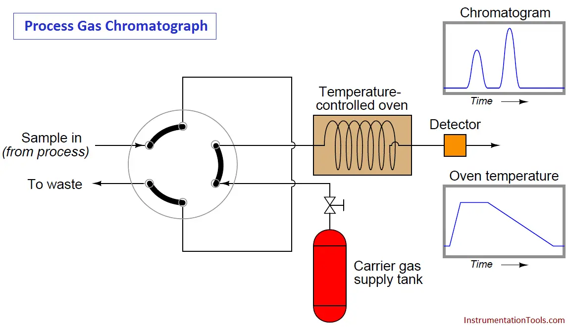
Temperature programming is an especially popular feature of process gas chromatographs, due to the direct effect temperature has on the viscosity of a flowing gas (Note2). Carefully altering the operating temperature of a GC column while a sample washes through it is an excellent way to optimize the separation and time delay properties of a column, effectively realizing the high separation properties of a long column with the reduced dead time of a much shorter column:
Note 2 : Whereas most liquids decrease in viscosity as temperature rises, gases increase in viscosity as they get hotter. In other words, a gas becomes “thicker” as it heats up, thus slowing down its progress through a chromatograph column. Since the flow regime through a chromatograph column is most definitely laminar and not turbulent, viscosity has a great effect on flow rate.
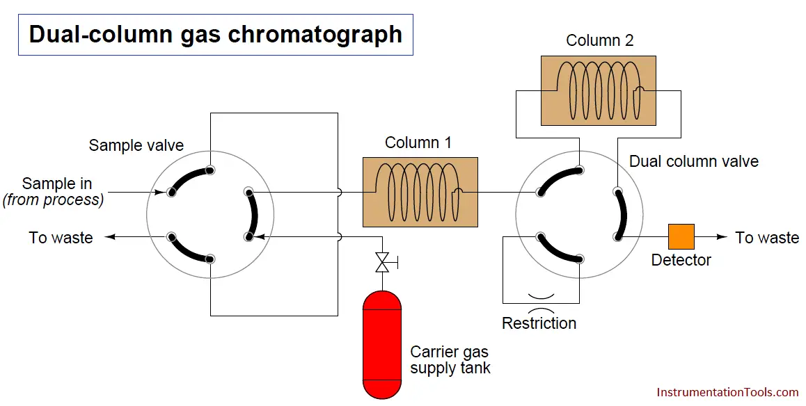
Note : Here for easy explanation, we are discussing a Dual Column Gas Chromatograph. In Industries we have more number of columns in a Gas Chromatograph.
Also Read : How GC Sample Valve Works ?
Another way to speed up the analysis time of a chromatograph is to design it with multiple columns and multiple switching valves, timing the valves so that only the fastest species travel through all columns, while slower species bypass later column stages to exit through the detector first. The alternative is to force all species to elute through all columns (or one long column), which means the minimum cycle time will be determined by the slowest species present in the sample.
To use the marathon analogy again, it’s like having to wait until the very last runner crosses the finish line before we can start another race to challenge faster runners. If, however, we stop the race mid-way to shuttle slow runners to the finish line (because we already know they are slow and will never win the race), we can still let the fastest runners compete the entire distance to determine who among them are the fastest, and thereby end the race sooner so we can move on to the next race:
A sequence for one type of dual-column gas chromatograph begins with the sample valve injecting a precise quantity of sample into the first column. In this illustration, the sample is comprised of 6 species labeled 1 through 6 in the order of their elution speed through the columns:
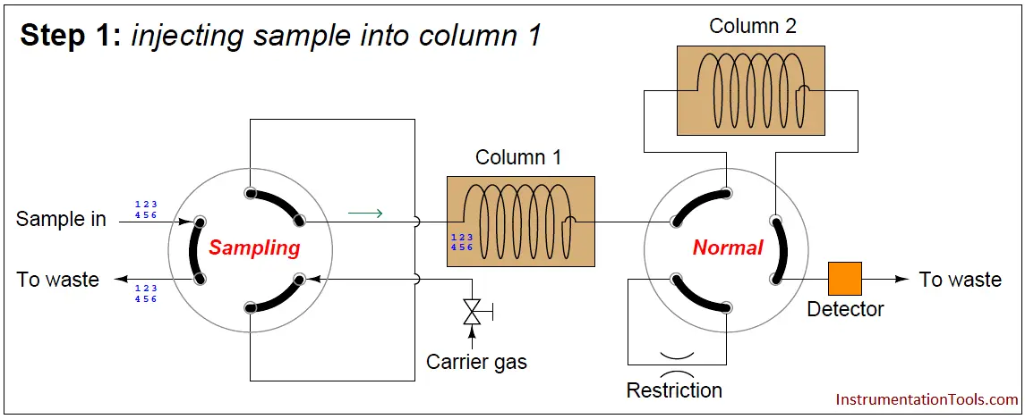
In the next step, the six species elute through column 1, with species 1 through 3 making it into the second column while species 4 through 6 are still residing in column 1:
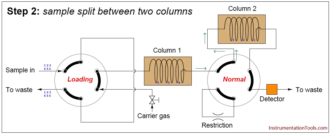
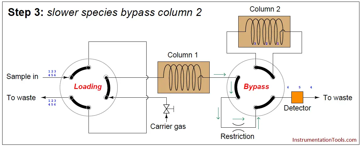
At this point in time, the dual-column valve switches into bypass mode, trapping the faster species (1 through 3) inside of column 2 while allowing the slower species (4 through 6) time to exit column 1 and pass through the detector:
In the last step, the dual-column valve switches back to its normal mode, allowing species 1 through 3 to elute through column 2 and pass through the detector:
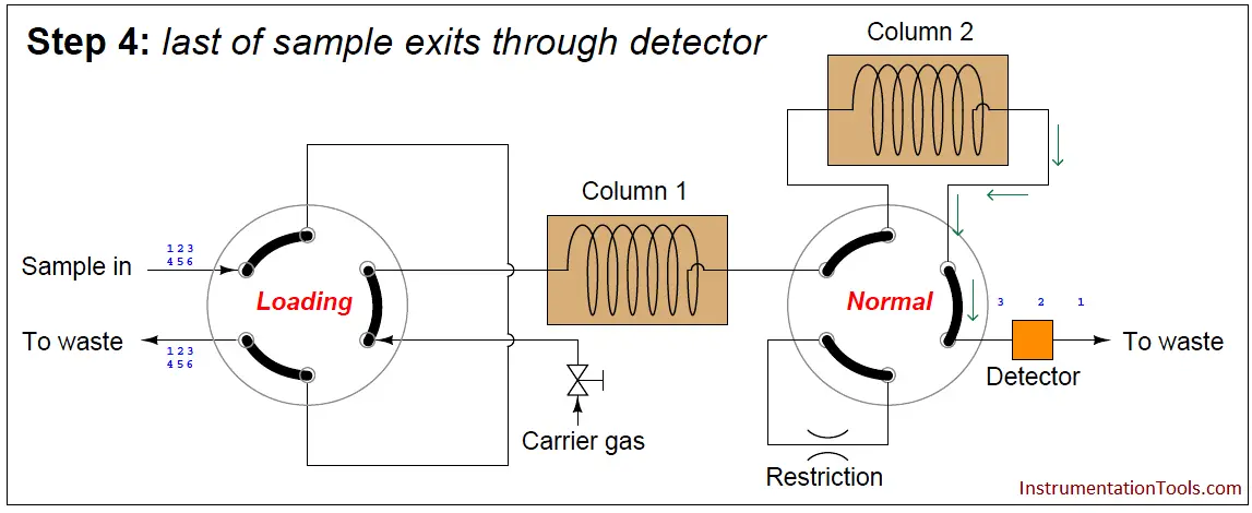
The dual-column valve’s timed switching from normal to bypass and back to normal again permits the slowest species to skip past the second column, while the fastest species must elute through both columns for maximum separation. This dual-column switching greatly reduces the total retention time of the sample without sacrificing separation of the fastest species/gas components (Note).
Note : Since the degree of separation between species is roughly proportional to the species’ retention time, the slowest species (4, 5, and 6 in this case) do not need to go through two columns to be adequately separated. It is only the fastest species needing more retention time (through an additional column) to separate adequately from one another.
A few noteworthy points must be raised with regard to multi-column chromatographs. First, the example shown in the preceding diagrams is not the only type of multi-column chromatograph. “Trapping” a series of sample compounds inside a column is not the only way to provide different compounds with different column paths for faster separation. Some multi-column chromatographs, for example, use “backflush” valves to reverse flow through one or more columns in an effort to avoid having the slowest species elute through the entire length of those columns. This technique is used in applications where separation among compounds in the “slow” group is not important, since backflushing tends to reverse any separation that took place in the column previously.
The next point regarding multi-column chromatographs is that the dual-column valve timing must be precisely set according to known retention times of the different species inside the different columns. In the example GC shown previously, this means the retention times of the transition species (3 and 4 in this case) through the first column must be precisely known, so the dual-column valve may be switched into bypass mode after species 3 exits the first column but before species 4 exits the first column. The retention time of the slowest species (6) must also be precisely known so that the dual-column valve will not switch back to normal mode too soon and route any of that species into the second column where it would take much more time to leave the system.
A final point regarding multi-column chromatographs is that the order of species progression through the detector will not be fastest to slowest as with single-column chromatographs. In the dual-column GC shown previously, the slower group will exit first in order of speed (4, 5, 6), then the fastest group will exit last in order of speed (1, 2, 3).
Also See : GC Working Animation


Gc Analyzer what is principle?
What is heart cut? Can u please explain