Inst ToolsInst ToolsInst Tools
  • Ask
  • Courses
  • Videos
  • Q & A
    • Interview
      • Instrumentation
      • Electronics
      • Electrical
      • Practical Questions
    • MCQ
      • Instrumentation MCQ
      • Electrical MCQ
      • Electronics MCQ
      • Control Systems MCQ
      • Analog Electronics MCQ
      • Digital Electronics MCQ
      • Power Electronics MCQ
      • Microprocessor MCQ
      • Multiple Choice Questions
  • EE
    • Electronics
      • Electronics Q & A
      • Electronic Basics
      • Electronic Devices & Circuits
      • Electronics Animation
      • Digital Electronics
    • Electrical
      • Electrical Basics
      • Electrical Q & A
      • Power Electronics
      • Electrical Machines
      • Electrical Animation
      • Power Systems
      • Switchgear & Protection
      • Transmission & Distribution
  • Measure
    • Control Valves
    • Calibration
    • Temperature
    • Pressure
    • Flow
    • Level
    • Analyzers
    • Switches
    • Vibration
    • Solenoid Valve
  • Control
    • PLC Tutorials
    • Control Systems
    • Safety Instrumented System (SIS)
    • Communication
    • Fire & Gas System
  • More
    • Design
    • Tools
    • Animation
    • Basics
    • Formulas
    • Standards
    • TextBooks
    • Common
    • Software
    • Excel Tools
    • Erection & Commissioning
    • Process Fundamentals
    • Videos
    • Books
Search
All rights reserved. Reproduction in whole or in part without written permission is prohibited.
Reading: Allen Bradley Studio 5000: Motor Running Hours PLC Program
Share
Notification Show More
Font ResizerAa
Inst ToolsInst Tools
Font ResizerAa
  • Courses
  • PLC Tutorials
  • Control Systems
Search
  • Ask
  • Courses
  • Videos
  • Q & A
    • Interview
    • MCQ
  • EE
    • Electronics
    • Electrical
  • Measure
    • Control Valves
    • Calibration
    • Temperature
    • Pressure
    • Flow
    • Level
    • Analyzers
    • Switches
    • Vibration
    • Solenoid Valve
  • Control
    • PLC Tutorials
    • Control Systems
    • Safety Instrumented System (SIS)
    • Communication
    • Fire & Gas System
  • More
    • Design
    • Tools
    • Animation
    • Basics
    • Formulas
    • Standards
    • TextBooks
    • Common
    • Software
    • Excel Tools
    • Erection & Commissioning
    • Process Fundamentals
    • Videos
    • Books
Follow US
All rights reserved. Reproduction in whole or in part without written permission is prohibited.
Inst Tools > Blog > PLC Tutorials > Allen Bradley Studio 5000: Motor Running Hours PLC Program

Allen Bradley Studio 5000: Motor Running Hours PLC Program

Discover how to write a PLC program for calculating and controlling motor running hours in the Rockwell Studio 5000 platform.

Last updated: September 20, 2024 6:07 am
Viral Nagda
PLC Tutorials
No Comments
Share
5 Min Read
SHARE

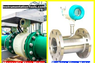
Motor running hours are an extremely important parameter in industrial automation. It is necessary to calculate it for efficient performance, maintenance, and switching of multiple motors.

Contents
Motor Running Hours PLC ProgramAllen Bradley Studio 5000

Motor Running Hours PLC Program

In the PLC program, motor running hours can be implemented with the help of timers and counters. In this post, we will see how to write a PLC program for calculating and controlling motor running hours using functional block diagram language in the Studio 5000 platform.

Let us understand the scenario first. We simply have a motor run feedback which we use to calculate the running hours. As the run feedback is received, the values start to accumulate in seconds, minutes, and hours.

We have a total runtime of 32000. After these hours, the counting will stop and the operator needs to press the reset button to again restart the counting.

Allen Bradley Studio 5000

For this, we use Studio 5000 software (Rockwell Automation) and implement it in functional block diagram language.

Let us understand the logic now. Refer to the below image. We will see each and every link one by one. We will use the following tags for HMI – I_Run_Cmd, I_Reset_Pb, DutyRunHrs_S_Pv, DutyRunHrs_S_Pv and DutyRunHrs_S_Pv.

Allen Bradley Studio 5000: Motor Running Hours PLC Program

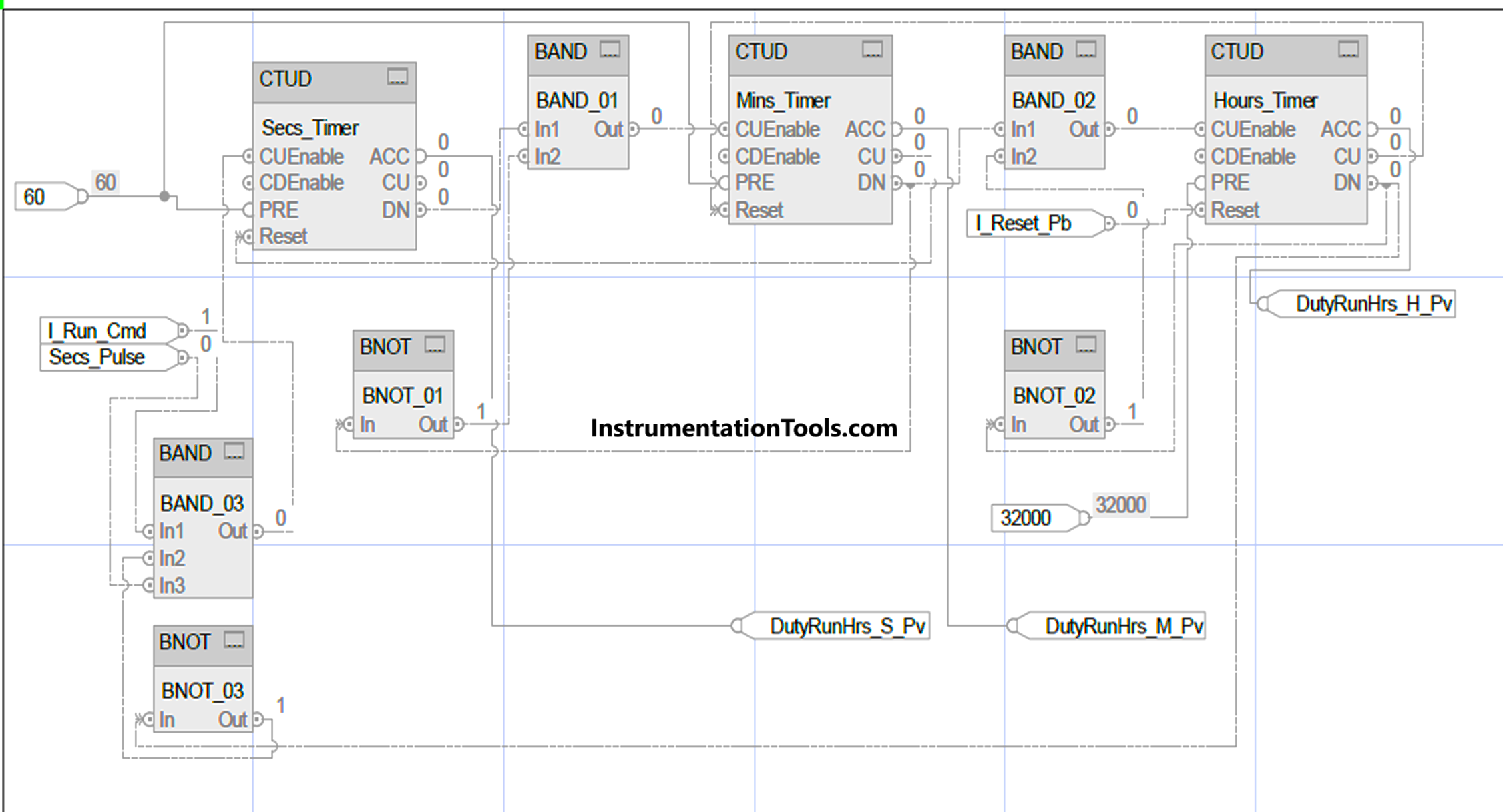
We will first start with counting seconds. Refer to the below image, which has all the links for a seconds counter. The blue color highlighted shows the link to this counter.

For counting the counter, we use an AND logic of run feedback, seconds pulse, and a negated version of the hours counter done bit. So, when the total hours are counted, it will block further counting.

We reset the counter when the minute counter is incremented every time. For this, we use a CU or count-enabled bit of the counter. Due to this, the succeeding counter will be incremented first and the preceding counter will be reset afterwards.

The accumulated value of this counter is written in a tag – DutyRunHrs_S_Pv. The done bit of this counter is used to increment the minutes counter. We use a set value of 60 for this counter.

Allen Bradley motor hours control

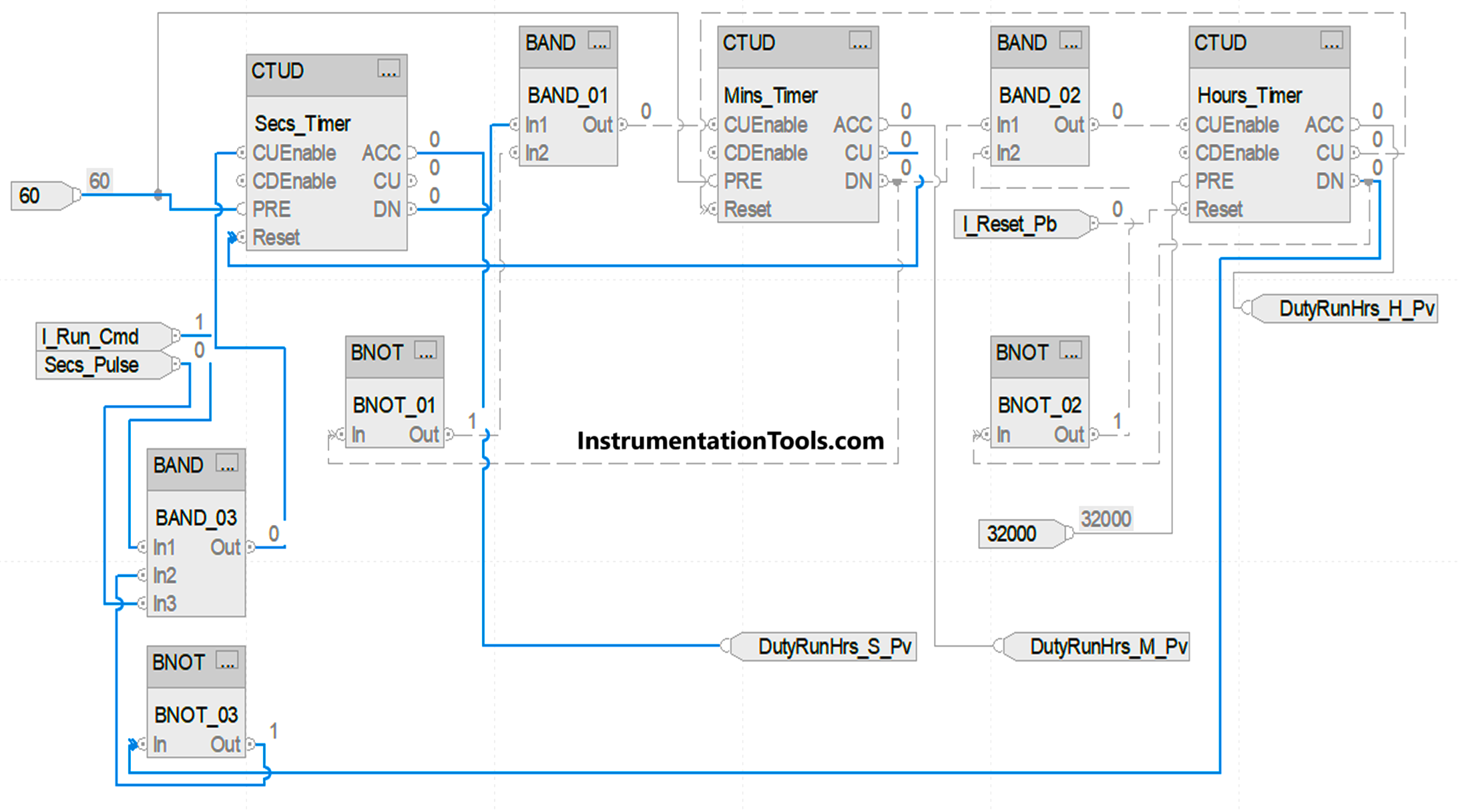
We next do counting minutes. Refer to the below image, which has all the links for a minutes counter. The blue color highlighted shows the link to this counter. For counting the counter, we use an AND logic of seconds counter done bit and a negated version of minutes counter done bit.

We reset the counter when the hour counter is incremented every time. For this, we use CU or count enabled bit of the counter. Due to this, the succeeding counter will be incremented first and the preceding counter will be reset afterwards.

The accumulated value of this counter is written in a tag – DutyRunHrs_M_Pv. The done bit of this counter is used to increment the hours counter. We use a set value of 60 for this counter.

Hour meter programming in Rockwell

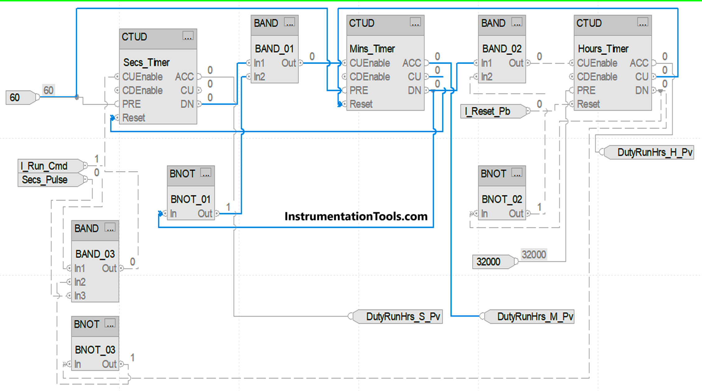
We next do counting hours. Refer to the below image, which has all the links for a hours counter. The blue color highlighted shows the link to this counter. For counting the counter, we use an AND logic of minutes counter done bit and a negated version of hours counter done bit.

We reset the counter when the user presses the reset button. The accumulated value of this counter is written in a tag – DutyRunHrs_H_Pv. The done bit of this counter is used to block the seconds counter. We use a set value of 32000 for this counter.

How to program a running hours meter in PLC

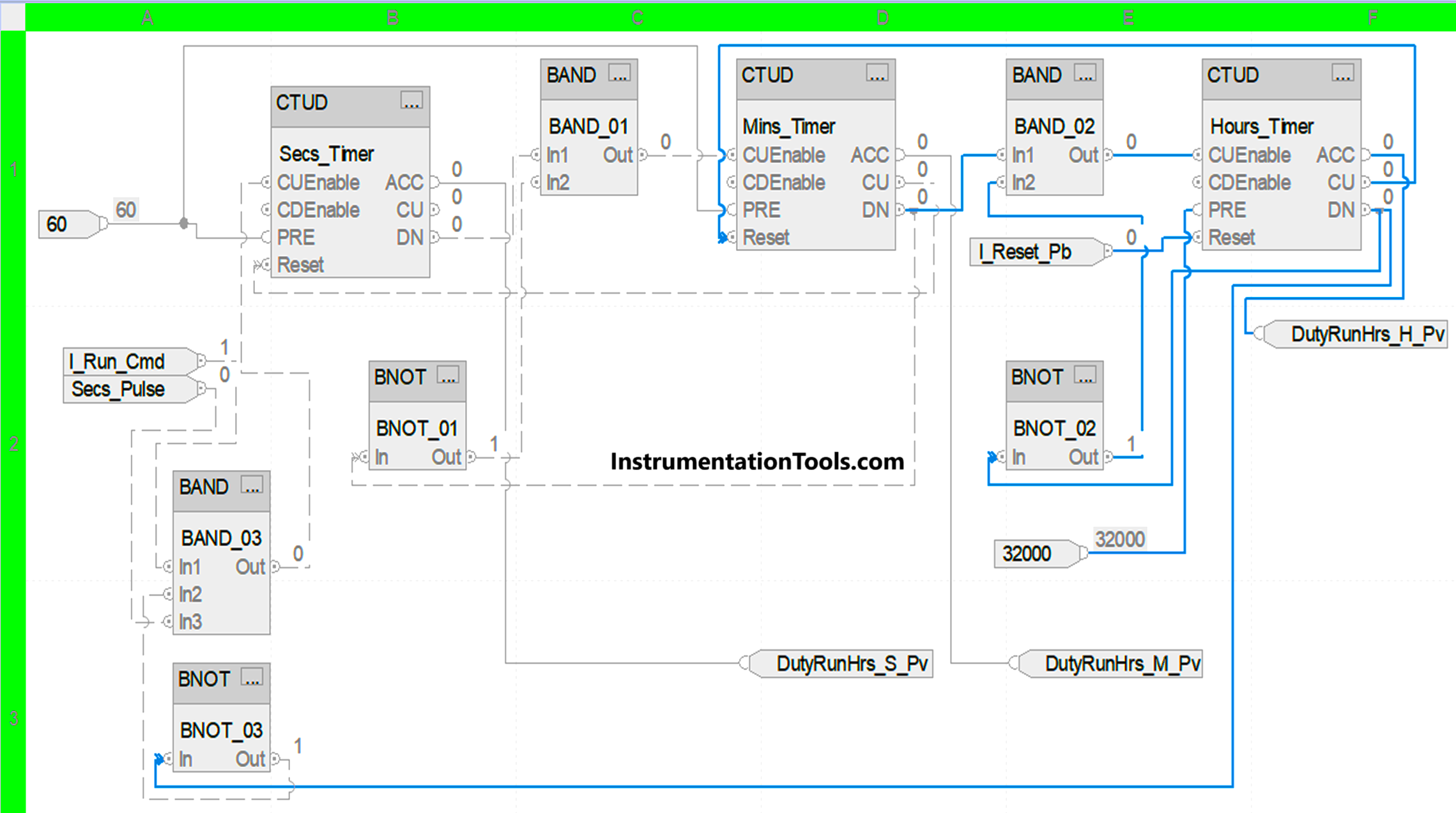
When the hours timer is done, the whole counting is stopped and not counted until the user presses the reset button. After this, the counting will start again from zero.

In this way, we saw how to write a PLC program for motor running hours using functional block diagram language.

Read Next:

  • Motor Starter Logic using Siemens PLC Logic
  • Structured Text PLC Logic for Motor Interlock
  • Car Wash Program Functional Block Diagram
  • Siemens VFD Configure TIA Portal Start drive
  • Configure PID Controller in Schneider PLC

Don't Miss Our Updates
Be the first to get exclusive content straight to your email.
We promise not to spam you. You can unsubscribe at any time.
Invalid email address
You've successfully subscribed !
Difference Between Microcontroller and PLC
Test and Process Modes in Siemens PLC
S7-1200 Hardware Configuration – Siemens PLC Tutorials
PLC Conveyor Motor Ladder Logic
What is Resources Tab in the Siemens PLC?
Share This Article
Facebook Whatsapp Whatsapp LinkedIn Copy Link
Share
Leave a Comment

Leave a Reply Cancel reply

Your email address will not be published. Required fields are marked *

Stay Connected

128.3kFollowersLike
69.1kFollowersFollow
208kSubscribersSubscribe
38kFollowersFollow

Categories

Recent Comments

  • Guifty Shimica on Top Non-PLC Certification Courses for Automation Professionals
  • Guifty Shimica on Top Non-PLC Certification Courses for Automation Professionals
  • MIHARITSOA Aina Sitraka on Top Non-PLC Certification Courses for Automation Professionals
  • Vaishnavi on Free Instrumentation Course for Trainee Engineers

Related Articles

Upgrading and Migration of PLC Systems

Upgrading and Migration of PLC Systems

Control system architecture diagrams

Vendor Document for Project Systems Architecture

Automatic Liquid Mixing Application

PLC Program for Automatic Liquid Mixing Application

Best PLC for Your Project

Finding the Best PLC for Your Project – Tips and Tricks

Digital Output Card With Relay and Wet Contact

Wiring Diagrams of PLC and DCS Systems – DI, DO, AI, AO

PLC Programming Software

What Factors Affect the Choice of PLC Programming Software?

Sink or source PNP or NPN Normally Open or Normally Closed Input v. output. output

Sink or Source? Normally Open or Normally Closed?

Scaling in PLC

How to do Scaling for Analog Input in RSLogix 500?

More Articles

Siemens PLC Simulator and Plant Simulation Software

How to use Simulator in Siemens PLC?

Reformer Tube Stress Relief Reusable Furnace

Miscellaneous Electrical Tasks – Repaired Reformer Tubes Weld Stress Relief

Burning Oven PLC Program

PLC Program for Ceramic Burning Oven Conveyor System

Control Valve Recommended Practices

Control Valve Recommended Practices for Harsh Process Conditions

What is an RTD

Components of RTD

Electric Circuits Objective Questions

Electric Circuits Objective Questions – Set 14

Why Silicon is preferred over Germanium ?

Why Silicon is preferred over Germanium ?

Level Gauge Theory

Types of Level Gauges

Follow US
All rights reserved. Reproduction in whole or in part without written permission is prohibited.
Welcome Back!

Sign in to your account

Username or Email Address
Password

Lost your password?