It seems very easy when someone asks an engineer to measure current. But, there are many interesting facts and things which need to be considered before measuring it. Because in the technology of electrical engineering, current measurement is a very important aspect for all the basic foundation and troubleshooting. They obviously depend on a multimeter for measurement, but even in that, there are some important points to note down before starting measurement. In this post, we will see some things to know when measuring current.
Current is most preferred to be measured in series
The measuring instruments like a multimeter or ammeter have a very low resistance. Unlike voltage which is measured in parallel (which means connecting the red probe to the positive terminal and connecting the black probe to the negative terminal), current should be measured in series due to this reason.
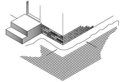
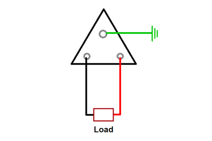
Refer to the below image. If you were measuring voltage, then you would have directly connected multimeter probes to any of the load or source points.
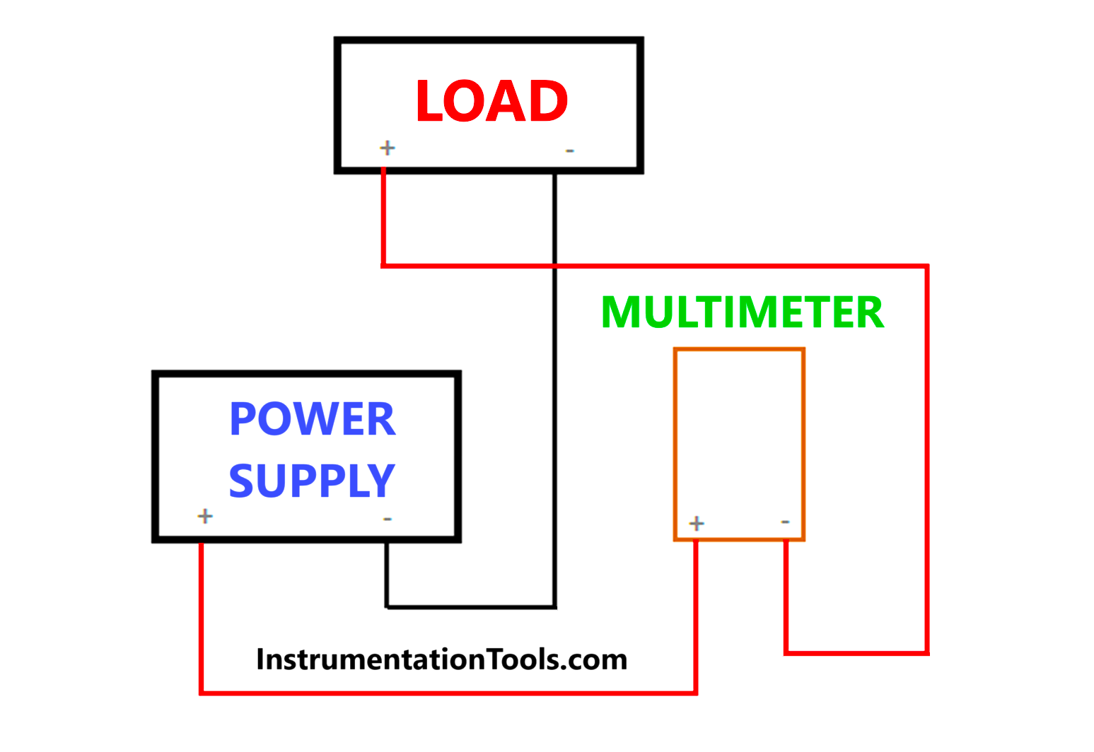
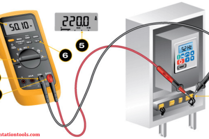
But when measuring current, you cannot do this thing. Because of the low resistance and normal fuse ratings used inside the meter, a very high current will flow through it and damage the meter. So, you need to break the circuit between the source and load and connect the multimeter in between.
The current from the source will flow through the meter as shown, and then reach the positive end of the load. The meter will directly measure the current in series, and show you the readings in ampere.
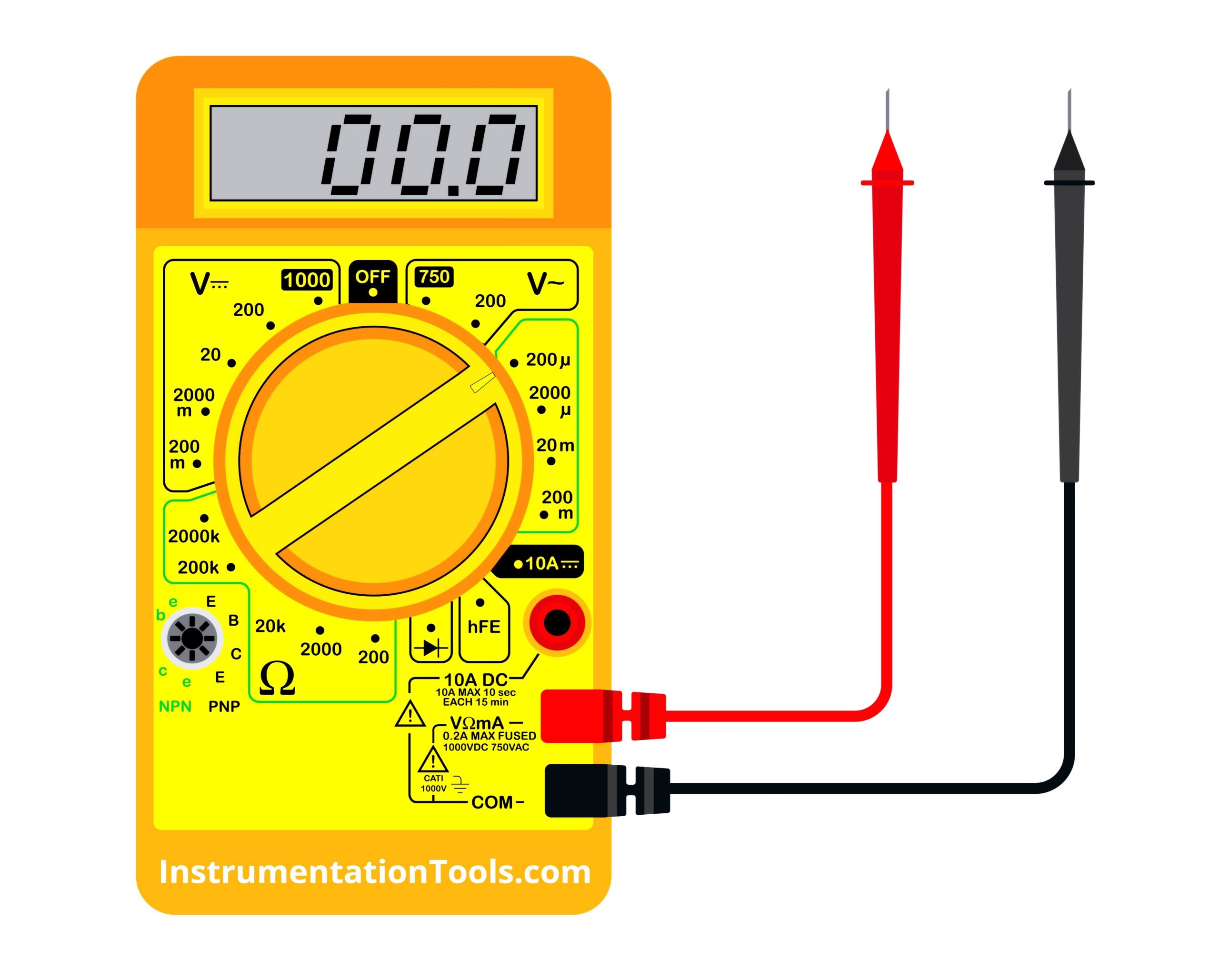
Set the meter in proper amperage ratings before connecting
You know whether DC or AC current is flowing in the circuit. You also know the maximum current that the load will carry. Standard multimeters have a maximum rating of 10 A. So, set the meter in that reading before measuring the current.
Also, when measuring current, it is recommended to first power off the circuit, then connect your probes, then power on the circuit and check the values. Meters also have a provision of milliamperes reading. So it should not be like you are measuring a heavier load and putting the probe in this range. It will damage the meter.
So check the ratings and probe before putting the meter in a live circuit. If the current you know is within the range of the ratings, then it can be connected in parallel ( but this is mostly recommended for milliamperes).
Use clamp meters for larger currents
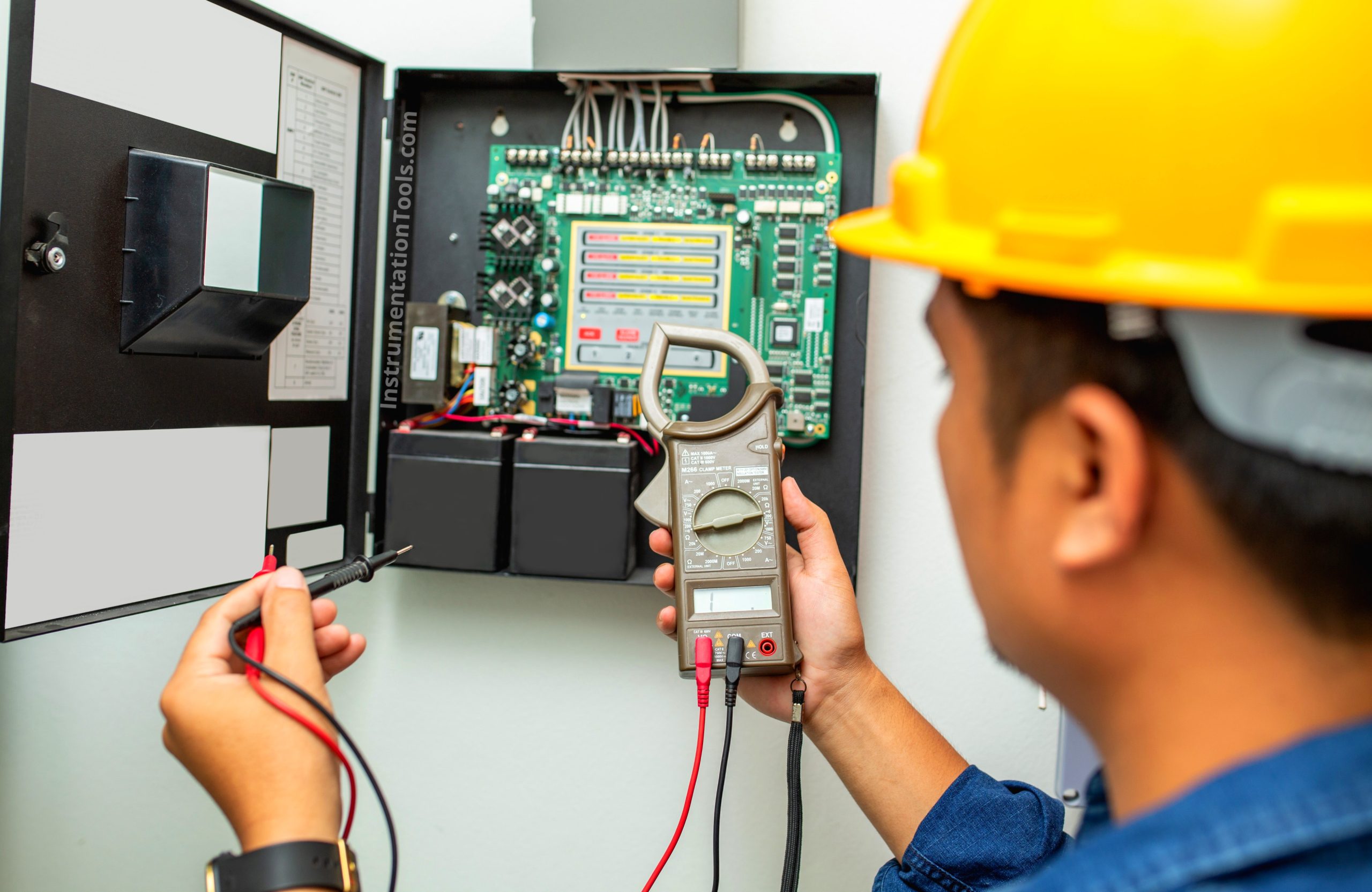
The clamp meter is the easiest way to measure current (uses magnetic fields to determine current flow). Just put the round clamp around the wire (like a current transducer) and check the values in the meter. This is most preferred as there is no need to close the circuit like in a multimeter, and you can check it live.
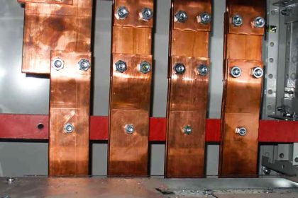
Also, larger currents provide a chance of an electrical shock; so clamp meters are preferred for larger values of currents. It is best used for checking busbar currents or other heavier loads where touching the circuit is not possible. But, clamp it around a single wire. If it is clamped around two wires, the magnetic fields will cancel each other and you will get a proper reading.
Use of PPE when measuring larger currents
Safety consideration is a must when measuring currents of large values. So, it is recommended for engineers to wear protective kits like gloves, safety glasses, or flame-resistant clothing. This will protect them from any potential hazard or accident.
Transient currents are difficult to capture
You know that a particular circuit has been affected by noise and causing disturbances in the system. You cannot connect a meter and monitor it continuously. It is cumbersome and tiring, as you do not know when the peak or harmonic or transient current will come
So, instead of manually and visually waiting for the current to occur, use a digital oscilloscope of high speeds, which can detect rapid changes. As it shows values in a graphical form, you can detect when the last transient occurred seeing date and time, and also check how frequently it is occurring. This quickly aids the troubleshooting process for the engineers.
Regular calibration is a must
Meters are affected by accuracy too, when frequent usage can affect the circuits inside. So, meters must be regularly calibrated for accuracy and reliability.
Accuracy can be affected due to incorrect connections, external temperature effects, or electromagnetic interferences. So, it is recommended to maintain a schedule for calibrating the meters and replacing them if found faulty or way too inaccurate.
In this way, we saw some important things to know when measuring current.
Read Next:
- Introduction to Protective Systems
- Implement Motor Control Circuits
- Ground fault trip of Circuit breaker
- Interesting Multimeter Functions
- Compare Clamp Meter and Multimeter