Inst ToolsInst ToolsInst Tools
  • Courses
  • Automation
    • PLC
    • Control System
    • Safety System
    • Communication
    • Fire & Gas System
  • Instrumentation
    • Design
    • Pressure
    • Temperature
    • Flow
    • Level
    • Vibration
    • Analyzer
    • Control Valve
    • Switch
    • Calibration
    • Erection & Commissioning
  • Interview
    • Instrumentation
    • Electrical
    • Electronics
    • Practical
  • Q&A
    • Instrumentation
    • Control System
    • Electrical
    • Electronics
    • Analog Electronics
    • Digital Electronics
    • Power Electronics
    • Microprocessor
  • Request
Search
  • Books
  • Software
  • Projects
  • Process
  • Tools
  • Basics
  • Formula
  • Power Plant
  • Root Cause Analysis
  • Electrical Basics
  • Animation
  • Standards
  • 4-20 mA Course
  • Siemens PLC Course
Reading: How to use Master Control Reset (MCR) Instruction in PLC
Share
Font ResizerAa
Inst ToolsInst Tools
Font ResizerAa
  • Courses
  • Design
  • PLC
  • Interview
  • Control System
Search
  • Courses
  • Automation
    • PLC
    • Control System
    • Safety System
    • Communication
    • Fire & Gas System
  • Instrumentation
    • Design
    • Pressure
    • Temperature
    • Flow
    • Level
    • Vibration
    • Analyzer
    • Control Valve
    • Switch
    • Calibration
    • Erection & Commissioning
  • Interview
    • Instrumentation
    • Electrical
    • Electronics
    • Practical
  • Q&A
    • Instrumentation
    • Control System
    • Electrical
    • Electronics
    • Analog Electronics
    • Digital Electronics
    • Power Electronics
    • Microprocessor
  • Request
Follow US
All rights reserved. Reproduction in whole or in part without written permission is prohibited.
Inst Tools > Blog > PLC Tutorials > How to use Master Control Reset (MCR) Instruction in PLC

How to use Master Control Reset (MCR) Instruction in PLC

Last updated: March 4, 2021 3:17 pm
Editorial Staff
PLC Tutorials
2 Comments
Share
5 Min Read
SHARE

A Master Control Reset (MCR) instruction is an output instruction. MCR instructions are always used in pair.

Contents
Master Control ResetProblem LogicList of Inputs and OutputsPLC MCR ProgramIf MCR Goes Off :Program DescriptionRUNG 0000RUNG 0001RUNG 0002 RUNG 0003RUNG 0004 RUNG 0005 and Rung 0006Rung 0007RUNG 0008RUNG 0009Conclusion:
MCR Instruction

The paired instructions cause the PLC to enable or inhibit a zone of ladder logic program outputs according the application logic. The zone being controlled is known as the MCR zone control. It begins with the rung that has the first MCR instruction. The MCR zone ends with the rung that has the second MCR instruction only.

Using this instruction, we can disable all the outputs at the same when MCR condition goes off.

Two MCR instruction are used to perform the function, One is to start the MCR zone with input condition as must and another one is to end the limit area.

An input condition like Emergency switch is programmed on the rung of the first MCR to control rung logic continuity. When the rung goes “false” all non-retentive outputs within the controlled zone are disabled. When the rung goes “true” all rungs are scanned according to their normal rung conditions.

No need to give any condition for closing MCR zone.

Let’s study the working of MCR using example,

Master Control Reset

Introduce MCR zone in automatic bottle filling system.

Automatic Bottle Filling System using PLC

Problem Logic

Step Conditions:

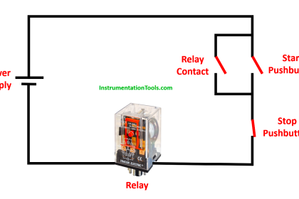
  1. Start and Stop PB is used to start and stop the process.
  2. MCR zone need to activated to start the process
  3. Start is pressed Conveyor starts moving until the Proximity Sensor is ON.
  4. Then solenoid valve is open for 5s. After 5s Conveyor should start moving.
  5. The above process should continue unto 3 bottles.
  6. Process should continue still stop push button pressed.
  7. In any emergency case, MCR condition goes off, all output disabled irrespective of its input.

List of Inputs and Outputs

MCR Instruction Example IO's

MCR zones let you enable or inhibit segments of your program, such as for recipe applications or subroutines.

If the MCR Rung that starts the zone is:

True

Executes the rungs in the MCR zone based on each rung’s individual input condition (as if the zone did not exist)

False

Resets all non-retentive output instructions in the MCR zone regardless of each rung’s individual input conditions
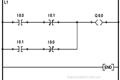
PLC MCR Program

Master Control Reset Instruction for Allen-Bradley
Master Control Reset (MCR) ladder logic
Master Control Reset and Zone Control

If MCR Goes Off :

see the below same ladder logic when the Master Control Reset (MCR) instructions becomes de-activated.

rslogix MCR Instructions
Examples of MCR block using PLC
PLC Program using Master Control Reset

Program Description

RUNG 0000

Latching rung to operate the system through Master Start and Stop PB.

RUNG 0001

MCR zone is introduced with input condition.

RUNG 0002

To turn ON Conveyor motor, memory bit (B3:0/1 ) is used .

 RUNG 0003

To turn on Conveyor motor using memory bit of start latching PB and B3:0/1, it will automatically turn off when B3:0/2 turns on once Proximity sensor activates. Timer done is connected in parallel to turn conveyor motor ON again.

RUNG 0004

Proximity sensor output saved in memory bit to use in previous rung.

 RUNG 0005 and Rung 0006

To store the status of proximity sensor B3:0/3 is used, Comparator block is used to compare counter accumulator value to stop the process once three bottle process had filled.

Rung 0007

To count the number of bottles, proximity sensor is given to up counter with preset value sets to 3.

RUNG 0008

Stop input is given to reset the counter.

RUNG 0009

MCZ zone is ended here.

Conclusion:

The above example of MCR explanation for simple bottle filling system. It may vary from real time.

Author : Hema Sundaresan

If you liked this article, then please subscribe to our YouTube Channel for PLC and SCADA video tutorials.

You can also follow us on Facebook and Twitter to receive daily updates.

Read Next:

How to Control VFD with PLC

Convert V to I using Resistor

Logical Instructions in PLC

Flow Meter Totalizer logic

PLC based Car Wash Program

Don't Miss Our Updates
Be the first to get exclusive content straight to your email.
We promise not to spam you. You can unsubscribe at any time.
Invalid email address
You've successfully subscribed !

Continue Reading

Redundant Automation Systems – Need and Advantages
InTouch SCADA Login Password Security
Single Push button to ON and OFF a Bulb using Ladder Logic
PLC Valve Control Ladder Logic Programming
Latching and Unlatching in PLC Programming Example
How to Export Data from WinCC Runtime Advanced into Excel using VB Script
Share This Article
Facebook Whatsapp Whatsapp LinkedIn Copy Link
Share
2 Comments
  • alvin says:
    May 30, 2020 at 11:50 pm

    very informative

    Reply
  • Facebook Marketing says:
    September 6, 2020 at 7:08 am

    Yeah bookmaking this wasn’t a bad decision great post!

    Reply

Leave a Reply Cancel reply

Your email address will not be published. Required fields are marked *

Stay Connected

128.3kFollowersLike
69.1kFollowersFollow
210kSubscribersSubscribe
38kFollowersFollow

Categories

Explore More

#10 PLC Best Practices – Assign Register Blocks by Function
How PLC Reads the Data from Field Transmitters
Motor Classic Control Circuits using Single Push button
Create a Function (FC) for a Valve Logic in Siemens PLC
Difference between PLC and HMI
PLC Permissive for Motor Control
All About Fieldbus Protocols
Siemens Tia Portal PLC Training Course

Keep Learning

PLC Motor Control Circuit-3

Basics of PLC Programming

Intrinsic Safety Barriers

Intrinsically Safe Barriers Questions and Answers

AI AO DI DO Signals

What are AI, AO, DI, and DO? – Definition, Examples, Purpose

21 CFR in SCADA and HMI Systems

What is 21 CFR in SCADA and HMI Systems?

Opposite Acting Control Valves Application

PLC Ladder Logic for Opposite Acting Control Valves Application

Free Mitsubishi PLC Online Training Courses

Free Mitsubishi PLC Online Training Course and Tutorials

Learn SCL programming from scratch

How to Start Writing SCL Language in Siemens Tia Portal?

What is a GSD File and Why it is required?

What is a GSD File and Why it is required?

Learn More

Sugar Plant - Automatic Control of Massecuite Feed

Sugar Plant – Automatic Control of Massecuite Feed

statuses of all lamps and relay coils in the circuit

Analyze the Relay Circuit and Find the Status ?

Instrumentation and Control Project Packages

Instrumentation and Control Project Packages – Detail Engineering

Sealed Bellows Temperature Sensors

Bellows Pressure Sensors Working Principle Animation

State Variable Analysis and Design

Concepts of State, State Variables & State Model

State Variable Analysis and Design

Observer Systems

Instrumentation and Control General Specifications

Instrumentation and Control (I&C) General Specifications

WHILE DO Statement in SCL Language

WHILE DO Statement in SCL Language

Menu

  • About
  • Privacy Policy
  • Copyright

Quick Links

  • Learn PLC
  • Helping Hand
  • Part Time Job

YouTube Subscribe

Follow US
All rights reserved. Reproduction in whole or in part without written permission is prohibited.
Welcome Back!

Sign in to your account

Username or Email Address
Password

Lost your password?