Inst ToolsInst ToolsInst Tools
  • Ask
  • Courses
  • Videos
  • Q & A
    • Interview
      • Instrumentation
      • Electronics
      • Electrical
      • Practical Questions
    • MCQ
      • Instrumentation MCQ
      • Electrical MCQ
      • Electronics MCQ
      • Control Systems MCQ
      • Analog Electronics MCQ
      • Digital Electronics MCQ
      • Power Electronics MCQ
      • Microprocessor MCQ
      • Multiple Choice Questions
  • EE
    • Electronics
      • Electronics Q & A
      • Electronic Basics
      • Electronic Devices & Circuits
      • Electronics Animation
      • Digital Electronics
    • Electrical
      • Electrical Basics
      • Electrical Q & A
      • Power Electronics
      • Electrical Machines
      • Electrical Animation
      • Power Systems
      • Switchgear & Protection
      • Transmission & Distribution
  • Measure
    • Control Valves
    • Calibration
    • Temperature
    • Pressure
    • Flow
    • Level
    • Analyzers
    • Switches
    • Vibration
    • Solenoid Valve
  • Control
    • PLC Tutorials
    • Control Systems
    • Safety Instrumented System (SIS)
    • Communication
    • Fire & Gas System
  • More
    • Design
    • Tools
    • Animation
    • Basics
    • Formulas
    • Standards
    • TextBooks
    • Common
    • Software
    • Excel Tools
    • Erection & Commissioning
    • Process Fundamentals
    • Videos
    • Books
Search
All rights reserved. Reproduction in whole or in part without written permission is prohibited.
Reading: Load Cell Working Principle
Share
Notification Show More
Font ResizerAa
Inst ToolsInst Tools
Font ResizerAa
  • Courses
  • PLC Tutorials
  • Control Systems
Search
  • Ask
  • Courses
  • Videos
  • Q & A
    • Interview
    • MCQ
  • EE
    • Electronics
    • Electrical
  • Measure
    • Control Valves
    • Calibration
    • Temperature
    • Pressure
    • Flow
    • Level
    • Analyzers
    • Switches
    • Vibration
    • Solenoid Valve
  • Control
    • PLC Tutorials
    • Control Systems
    • Safety Instrumented System (SIS)
    • Communication
    • Fire & Gas System
  • More
    • Design
    • Tools
    • Animation
    • Basics
    • Formulas
    • Standards
    • TextBooks
    • Common
    • Software
    • Excel Tools
    • Erection & Commissioning
    • Process Fundamentals
    • Videos
    • Books
Follow US
All rights reserved. Reproduction in whole or in part without written permission is prohibited.
Inst Tools > Blog > Animation > Load Cell Working Principle

Load Cell Working Principle

Last updated: August 22, 2018 5:30 pm
Editorial Staff
Animation Common How It Works
12 Comments
Share
5 Min Read
SHARE

Load cell is a sensor or a transducer that converts a load or force acting on it into an electronic signal. This electronic signal can be a voltage change, current change or frequency change depending on the type of load cell and circuitry used.

There are many different kinds of load cells.

Resistive load cells work on the principle of piezo-resistivity. When a load/force/stress is applied to the sensor, it changes its resistance. This change in resistance leads to a change in output voltage when a input voltage is applied.

Capacitive load cells work on the principle of change of capacitance which is the ability of a system to hold a certain amount of charge when a voltage is applied to it. For common parallel plate capacitors, the capacitance is directly proportional to the amount of overlap of the plates and the dielectric between the plates and inversely proportional to the gap between the plates.

How does a resistive load cell works ?

A load cell is made by using an elastic member (with very highly repeatable deflection pattern) to which a number of strain gauges are attached.

resistive load cell working

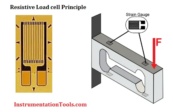
In this particular load cell shown in above figure, there are a total of four strain gauges that are bonded to the upper and lower surfaces of the load cell.

load cell in deflection

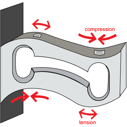
When the load is applied to the body of a resistive load cell as shown above, the elastic member, deflects as shown and creates a strain at those locations due to the stress applied. As a result, two of the strain gauges are in compression, whereas the other two are in tension as shown in below animation.

Load Cell Working Animation

During a measurement, weight acts on the load cell’s metal spring element and causes elastic deformation.

This strain (positive or negative) is converted into an electrical signal by a strain gauge (SG) installed on the spring element. The simplest type of load cell is a bending beam with a strain gauge.

We use wheatstone bridge circuit to convert this change in strain/resistance into voltage which is proportional to the load.

Load Cell Working Animation
Load Cell Principle

Wheatstone Bridge Circuit

The four strain gauges are configured in a Wheatstone Bridge configuration with four separate resistors connected as shown in what is called a Wheatstone Bridge Network.

An excitation voltage – usually 10V is applied to one set of corners and the voltage difference is measured between the other two corners. At equilibrium with no applied load, the voltage output is zero or very close to zero when the four resistors are closely matched in value. That is why it is referred to as a balanced bridge circuit.

Wheatstone Bridge Circuit

When the metallic member to which the strain gauges are attached, is stressed by the application of a force, the resulting strain – leads to a change in resistance in one (or more) of the resistors. This change in resistance results in a change in output voltage. This small change in output voltage (usually about 20 mVolt of total change in response to full load) can be measured and digitized after careful amplification of the small milli-volt level signals to a higher amplitude 0-5V or 0-10V signal.

These load cells have been in use for many decades now, and can provide very accurate readings but require many tedious steps during the manufacturing process

There are various load cell designs in addition to bending beams. This includes for example:

  • Load cells with column-shaped spring elements for high loads
  • Hollow cylindrical load cells for very high loads
  • Load cells with spring elements directly from the measuring bracket
  • Ring torsion load cells
  • Shear beam load cells
  • Load cells with diaphragm spring element.
Don't Miss Our Updates
Be the first to get exclusive content straight to your email.
We promise not to spam you. You can unsubscribe at any time.
Invalid email address
You've successfully subscribed !
What is an Instrument Skid? – Example of Metering Skid
How Does Starlink Work?
How Technology is Shaping the Future of Education?
Engineering Logic Diagrams
Pressure Regulator with Flapper-Nozzle Principle
Share This Article
Facebook Whatsapp Whatsapp LinkedIn Copy Link
Share
12 Comments
  • basavaraj teli says:
    October 5, 2016 at 5:14 pm

    Dear sir i am very happy to see such a useful website and it is good tool for beginners.. thanks a lot ..

    Reply
  • Ravi jalwal says:
    October 16, 2016 at 2:55 am

    Plz send me some short quistions & answers on all instrumentation.

    Reply
  • Jawed says:
    October 17, 2016 at 8:21 pm

    Very Nice Site.

    Reply
  • J.Balaraju Achary says:
    December 24, 2016 at 10:52 am

    Dear Sir, Very useful to us

    Reply
  • Subash raja says:
    January 10, 2017 at 4:47 am

    Hi Sir,
    Can u explain about the use of overall shield and individual sheild and where we have use IS and non IS cable sir

    Reply
    • asif qureshi says:
      February 9, 2021 at 8:05 pm

      Applies for Multicore Instrument Pair Cables, If Each pair will have an individual shiled refer to IS and there will be an separater overall outer shield for all cores will refer to the overall shield. IS Cables are used for the Intrinsically Safe Circuit having Low Voltage and Current in Hazardous area application for Spark protection. Whilst the OS Cable can be used for digital signal such as limit switch, pressure switches etc.

      Reply
  • manish wadia says:
    March 16, 2017 at 1:25 pm

    Dear,,sir thankx….for valuable information,,,about.load cell…thankx.,.again

    Reply
  • nasim says:
    August 22, 2019 at 8:07 pm

    Awesome

    Reply
  • Pradip says:
    September 27, 2020 at 5:31 pm

    sir my question is why bridge requires negative and positive voltage as a supply…..?

    Reply
  • Nikolaos Papadakis says:
    July 13, 2021 at 9:52 am

    Could you explain why some bending beam load cell designs are not affected by the exact loading point? So if you placed the load a bit further away they still measure the same value.

    Reply
  • Zubair Rasheed says:
    February 3, 2023 at 11:27 am

    sir i have question regarding loadcell if a loadcell has let suppose weight is 750kg and excitation voltage is 10V what is return mv/v kindly explain it briefly

    Reply
  • Optima Weightech says:
    December 14, 2023 at 3:21 pm

    Thank you for sharing the detailed guide on the working mechanism of a load cell, with proper diagrams and creative assets.

    Reply

Leave a Reply Cancel reply

Your email address will not be published. Required fields are marked *

Stay Connected

128.3kFollowersLike
69.1kFollowersFollow
208kSubscribersSubscribe
38kFollowersFollow

Categories

Recent Comments

  • Kamli on Top Free PLC Software
  • Guifty Shimica on Top Non-PLC Certification Courses for Automation Professionals
  • Guifty Shimica on Top Non-PLC Certification Courses for Automation Professionals
  • MIHARITSOA Aina Sitraka on Top Non-PLC Certification Courses for Automation Professionals

Related Articles

Pneumatic Level Control Valve

Piping and Instrumentation Drawing (P&ID) Tutorials – Part 3

Oval Gear Flow Meter Principle

Oval Gear Flow Meters – Principle, Advantages, Animation

Dome Valve Principle

Dome Valve Working Principle

Robotic Process Automation

What is Robotic Process Automation? Advantages, Applications

Total Organic Carbon Analyzer Working Principle

TOC Analyzer Working Principle

Electricity Generated From Wind Energy

How is Electricity Generated From Wind Energy?

Career Opportunities and Scope in Industrial Automation

Career Opportunities and Scope in Industrial Automation

Vibrating Fork Level Switch Working Animation

Vibrating Fork Level Switch Working Animation

More Articles

Transformer voltage and turns ratio

Transformer Current Ratio

multiphase-flowmeter-working-principle

What are Multiphase Flow Meters? – Working Principle, Advantages

PLC Tag Naming Conventions

PLC Tag Naming Conventions

Flow Switch Symbol

Principle of Flow Switch

Heat Exchanger Baffles Holes

Heat Exchanger Tubes Corroded Root Cause Analysis

Communication between Intouch Scada and Allen Bradley PLC

Communication between InTouch Scada and Allen Bradley PLC

refrigeration compressors

Why is CO2 the Most Promising Refrigerant in Cooling Industry?

DeltaV Tune Tutorial

How to Tune a Loop in DeltaV System

Follow US
All rights reserved. Reproduction in whole or in part without written permission is prohibited.
Welcome Back!

Sign in to your account

Username or Email Address
Password

Lost your password?